As the senior living descendant of the our Hogg Family, I have designed a new ‘Coat Of Arms’. Our male Family Tree that can be traced back starting with:
John Hogg (1750)
John Hogg (1806)
William Hogg (1836)
William Hogg (1866)
Edward Hogg (1888) (Grandfather)
Joseph Lishman Hogg (1918) (Father)
Bryan Hogg (1941)
KM Hogg (1964) (Son)
The Hogg Surname Origin
The Hogg Surname Origin is from Scotland, North East of England and Ireland. My Family originated and remained with my birth in 1941 in Gateshead Upon Tyne in the North East of England.
A twelve image animation produced “Animal Instinct/Photo of Daniel Lee” at San Antonio Museum of Art, (2011) shown below. It is extremely well done but is the theory of ‘Evolution’ true?
Did all the Species Evolve from Fish?
There are millions of Species on this Planet; Insects, Mammals, Birds, Reptiles and supposedly 65 million years ago Dinosaurs. Did all of these evolve from Fish? I find it hard to believe that is true. There is so much about Humans and other Species existence on this Planet and the Universe that we really don’t know anything about. Our learned scientist and others like Darwin have created this ‘Theory of Evolution’ because it ‘fits’ the story based upon Human Bones and Fossils found on the Planet.
How did the Dinosaurs Evolve?
We all know about the Dinosaurs as once again we have discovered full size bone structures of these Reptilians and through scientific aging decided they existed 65 millions years ago. However, I don’t see much evidence of how the Dinosaurs evolved from Fish!! Even at that time we are told there were still many species of Insects and Fish and Mammals already on the Planet.
Field Museum of Natural History in Chicago, Illinois.
How did the Fish Evolve?
We are told that the Species Evolved from Fish. However, how did the Fish Evolve? The answer normally given is that all Species derived from micro organisms 530 million years ago that were on the Planet due to the environmental conditions on the Planet within the Water.
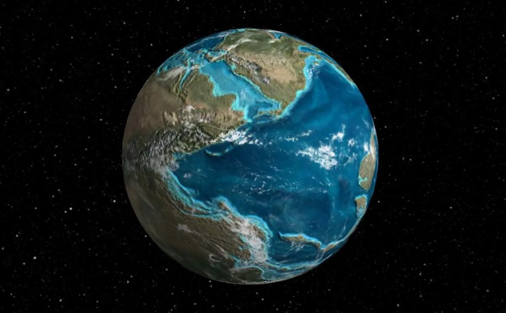
Planet Earth 500 Million Years Ago (Ma)
Our Planet is Microscopic in the Universe.
Planet Earth is like a micro dot in the Universe which we know about due to images and possible theories of its composition told to us by Astrophysicists. However, we know absolutely nothing about the existence of other forms of Intelligence far in advance of our own within the Universe. Note: I did not say Life Forms as that is based on our Human Form. Even today when we talk about outer space ‘Aliens’ we always portray them of having some form of body structure like the Humans, which maybe complete nonsense.
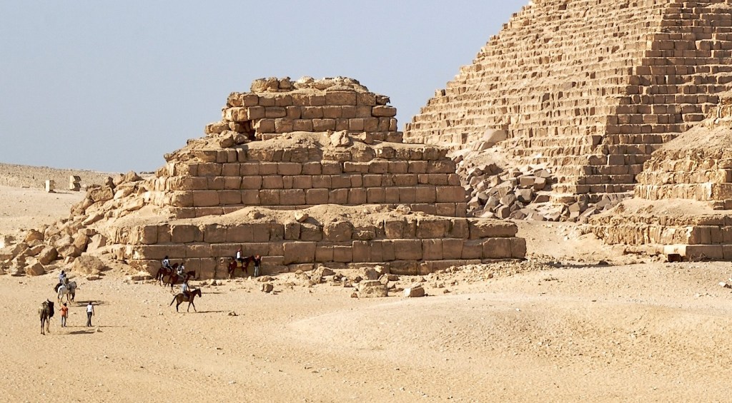
Did ‘Alien Intelligence’ insert Species on the Planet ?
This assertion that ‘Alien Intelligence’ inserted Species on the Planet millions of years ago sounds too ridiculous to be true because of the ‘Evolution Theory’. However, look at some of the structures on the Planet, such as old Cities constructed almost 8000 to 4000 years ago such as the Pyramids, Temples and others like Stonehenge. These were constructed mathematically to the millimeter using huge shaped stones weighing tons and interlocked in some cases. Many of this constructions were perfectly aligned with the Stars and/or the Sun. How did our ancestors know how to do this? The ‘Evolution Theory’ states that the Human at that time did not have the Knowledge, Skills and Tools to create such structures.
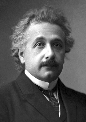
Super Human Brain Power
Is it possible that some Humans that have Super Brain Power such as Albert Einstein and many others that have been given super intelligence by Alien Intelligence to allow mankind to design and build advanced machinery, robotics, construction techniques and computers and computer software. As we see today we are creating Artificial Intelligence (AI) using the computers and AI software which does not have a Human body form. Even the inventors of AI are very concerned that one day that AI will be far more Intelligent than the Humans and a threat to mankind.
Albert Einstein
Just Thoughts
These comments are just thoughts that have no real answers. I am not alone in trying to think outside the box and realising we know very little about our existence, who we are and our purpose on this Planet. The Universe is so vast and our Planets existence within it so very small we have to always keep an open mind and wonder if their is a God in the form of super intelligence and all knowing.
I have noticed for the past years the increase in Anti-West Alliance Rhetoric especially from my second home in the Far East. It appears to all stem from the increase in Russia and in particular China’s move to alienate western democracy and values by trying to dismantle the World Order which has existed for the past 80 years. This is down to two autocrats, Putin and Xi Jinping who are blaming the West Alliances for the world problems of today and emerging ones of tomorrow. The West Alliance includes United States (US), Canada, United Kingdom (UK), European Union Countries, NATO Countries, Australia, New Zealand, Singapore, Philippines (Yellow) and other Far Eastern Countries who are being courted by China and are undecided who to support (Grey). White colour unknown alliance.
West Alliances and Democracy:
However, the West Alliances over the past years have contributed to its own demise with wars in Afghanistan and Iraq that promised Democracy which have created human and governance disasters due to lack of post war planning and implementation. The turmoil of the US Trump Presidency which has and still is having a major impact on the US and the Wests Alliances democracy itself. This has given the Adversaries of the West Alliances what they see, as reasons for change to the World Order. However, the extensive freedoms that the West Alliances Democracy model has to date should not be underestimated or forgotten by the Adversaries.
Threat to the West Alliances:
It is very noticeable that Russia and China have been increasing their influence on other world countries to oppose the the West Alliances and becoming Partners in their Autocratic world by the use of money in the form of grants and loans, resources such as oil and gas, technology and military equipment supply and the ideology of Autocratic Approach and Human Control under their ruling systems. These countries are major players such as India, Brazil, Iran, North Korea and many African Countries, (Purple) that are increasing which is significant and pose a real threat to the West Alliances.
The other very troubling issue is the rapid expansion of the Chinese Military who are now flexing their muscles in an aggressive manner although they say it is for defence only. Although China has never controlled Taiwan which has been a self ruling Democratic Island for almost a 100 years they have decided it is theirs. The same with the South China Sea which neither is accepted by the world bodies such as the United Nations (UN) or the West Alliance. In other words they just will do what they want and ignore the World Order which is what they are actively trying to destroy.
The Ukraine (Green) War started by Russia is part of the plot to regain the Soviet Union and once again with no regard to the world bodies or concerns. Like China who are now friends with Russia this suits the purpose of destabilising the World Order. This has been disastrous for the Energy provisions to Europe which relied so heavily on Russian Oil and Gas. It has also had an effect on Grain Supplies to other parts of the world.
As part of the threat to the West Alliance is the financial instability where countries are now actively trying to destroy the dominance of the US Dollar and other West Alliance Currencies like the Euro and Sterling by allowing transactions in their own Currencies or using the Chinese Yuan and/or the Russian Rouble for Oil, Gas and other products. This was evident in a recent visit to China by the new Brazilian President who is supporting China in their discussions regarding Currencies.
The West Alliance Response:
The threat to the West Alliance and the World Order is real and serious. It is no wonder that the West Alliance militarily is to increase their strength and deployment in Europe and the Far East for a potential World War 3 which no one will gain. The war in Ukraine and support by providing weapons is part of that required to prevent Russia acquiring Ukraine by Force which is against the World Order. The West Alliance has strengthened there military presence in the Far East including new access to Philippines bases to counter Chinese aggregation against Far Eastern Countries, Claiming and Occupying Islands in the South China Sea which do not belong to them and militarising them. In addition to signal to China that attacking Taiwan is not in their best interests.
Commercially the West Alliance is still reasonably strong and one of the Major markets of China products. The US Dollar, Euro and Sterling are still Major Trading Currencies. The Stock Markets of New York, London and Frankfurt are still the leading ones in the world. However, they need to protect against the rise as I have said in the movement away from the West Alliances Currencies.
A World Divided:
When I came into this world in 1941 it was divided between the Axis Nations (Nazi Germany, Japan and Italy) and the rest of the world including the UK, US, Canada, Australia, New Zealand, Russia and others in World War 2.
Today we have a world divided as we have discussed which hopefully will not result in World War 3 which will bring the world to an end as we know it today which no nation wants friend or foe. However, we must be realistic as the possibility is increasing every day of World War 3 maybe due to an Accidental Incident or a Preemptive Nuclear strike by any Nuclear nation.
From what I see everything revolves around the US, China and Russia who must sit round a table and discuss this whole issue. However, if China and Russia are hellbent on destroying the World Order through their actions as described above it seems impossible for that to happen.
Therefore, the West Alliances are going to have to adapt to this situation and create their own sphere of influence and systems which will physically divide the world into two different operating regimes, without military confrontation if at all possible. This will bring an end to Globalisation as we know it which will not benefit any nation, especially China, known as the workshop of the world where a great deal of trade with them will cease.
In the coming years given that we do not have World war 3, we will see the power of Oil and Gas diminish as Electrification increases and Nuclear Power and Renewable Power increases to provide the Electrical Power increase that is needed. This in itself will reduce the reliance on Oil and Gas producing countries, mainly Russia and the Middle East.
Conclusion:
The shift in support for China in particular in the Far East is mainly due to fear of China and its influence in this area, promising more trade and financial support for big projects to benefit the smaller countries. More people are surprised and admire the advancement of China’s infrastructure and wealth gained by supplying the world with goods of all types when they visit China.
In real terms China holds the key to the future relationship with the West Alliance and we can only hope that some form of mutual understanding and compromise can be found to make the world a safer place.
As Confucius’ said “The superior man, when resting in safety, does not forget that danger may come. When in a state of security he does not forget the possibility of ruin. When all is orderly, he does not forget that disorder may come. Thus his person is not endangered, and his States and all their clans are preserved.”
Perhaps all should consider consider this saying to avoid a world catastrophe of immense proportion.
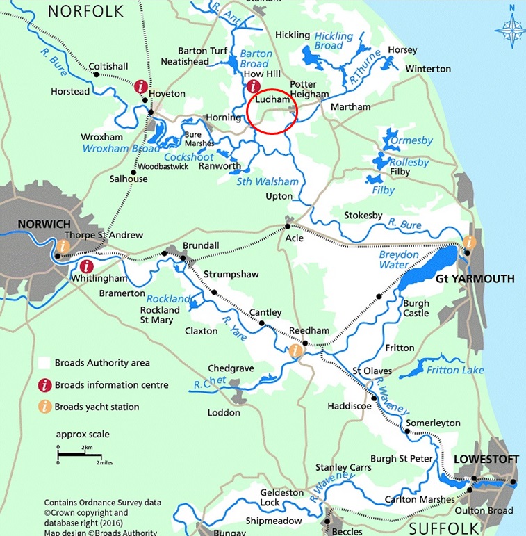
Ludham Village is located in the county of Norfolk, England, Great Britain about 15 miles from Norwich City and about 8 miles from the North Sea. The earliest record of Ludham is 1016 when King Cnut founded St. Benet’s Abbey. Ludham was the most easterly Royal Air Force (RAF) Airfield during the second world war, created in 1941, with many fighter aircraft such as the Spitfires and Typhoons. HM King George VI and Queen Elizabeth visited the Base in late January 1943. It was also allocated to the US Air Force but never used by them. Ludham is surrounded by farms and waterways and is a close knit community with a rich history.
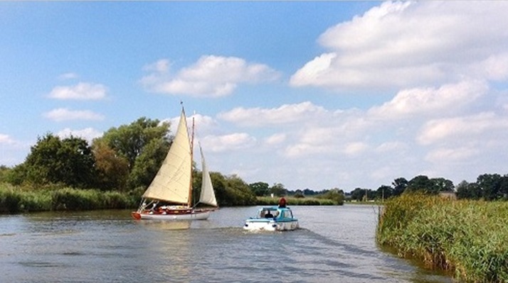
Ludham is part of a combination of Rivers, Broads (Lakes) and other waterways called the Norfolk Broads. These are part of the national parks and are used by holiday makers hiring Yachts, Motor Cruisers and smaller Boats.
My association with Ludham has 2 parts both related to my Father, Joseph (Joe) Hogg and my Mother Margaret (Peggy) Hogg. The first part was from 1946 to 1951 when we moved to Ludham from my home town Gateshead-On-Tyne, Co Durham. The second part when my parents moved from Keighley, Yorkshire in 1962 until about 2008 after my mother passed away in 2004 and later my father passed away aged 95.
The following is my own recollection of those times remembering I am now 82 years old and our memories can be a bit blurred at times but I will always have a great affection for Ludham and the people I met. This is story is dedicated to my Children, Grandchildren and Great Grandchildren.
The Norfolk Broads including the Suffolk Broads – Identifying Ludham Village
Part 1 – Ludham 1946 to 1951
A few months after the second World War finished in June 1945 my Father, Mother, Sister 3 years old and I, nearly 5 years old moved to a village in Norfolk called Ludham. My Father who I called ‘Dad’, a Non Ferrous Moulder who helped to build war ships in Gateshead- upon-Tyne in North East England, where my sister and I were born, moved to become a partner in a small Non Ferrous Foundry established as R.O Brooks, in the village of Ludham Norfolk. When we arrived we first lived in a very small house on Staithe Road next to the Churchyard and Cemetery near the centre of the village.
Ludham Village High Street in the 1950’s and the road to our small HouseThe Small House on Staithe Road where we first lived when arriving in Ludham in 1946
Primary School:
When I was 5 year old in 1946 I went to the Ludham Primary School on School Road near the village centre which is still there exactly as it was except for some modernisation. I remember our Head Master called Mr Bird who I met in the village many years later. These are pictures of me at the Ludham Primary School at the age around 7 years old. I went to school with Tommy Thrower, Jenny Roll, Malcolm and Jill Parker and others I don’t remember but we were also very good friends but a bit rebellious sometimes which led us into trouble with Mr Bird. Later my Sister Audrey who is 18 months younger than me also went to the same school and was also friends with Jill Parker.
Ludham Primary School and me at the same School around 1948
Brooks Foundry – My Dad:
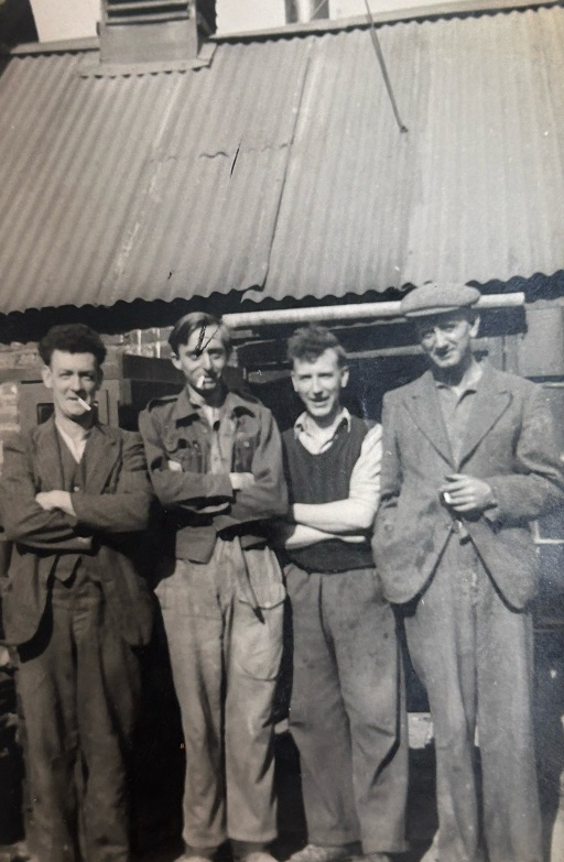
The R.O Brooks Foundry was located behind the cottages on Norwich Road. My Dad who was a very skilled Non Ferrous Moulder, joined Russel Brooks in 1946 to expand the business. The image is my Dad (far left) with his Workmates outside the small Foundry.
The Brooks Foundry was located behind these CottagesMy Father Joe Hogg (far left) with Workmates at the Foundry
My Dad liked his pint of Beer in moderation and was a very good dart player. He used to play for both the Kings Arms and Bakers Arms teams. I remember my Dad took me into the pubs for a very short time just to see what it was like when I was around 8 years old.
The Kings Arms and Bakers Arms village pubs
Manor Farm – Malcolm Parker:
Malcolm Parker was about the same age as me and we went to school together. His Father owned Manor Farm which was on Staithe Road on the corner with Lovers Lane on the way to Cold Harbour. Malcolm and I went everywhere together and got into trouble together as we were both young rebels. I used to go to the Farm quite often as it was on the way when we went Fishing or just mess about at Cold Harbour. They had some black and white Friesian Cows which they used to milk everyday. I remember Malcolm, me and some other boys went out to get Chestnuts to play Conkers. However, to get them we used to throw stones or small bricks to get them off the tree. However one of the small bricks fell on one of the boys head who went off crying and telling us he would tell the policeman. So we all decided to walk round the Marshes so we would not get into trouble. Wrong, when Malcolm and I reached my small house in the evening the local policeman was talking to my Dad. We both got scolded.
One year in a field opposite owned by Malcolm’s Dad was used to erect a big Circus Tent and all the different things and animals that a Circus has. Malcolm and I used to go and watch what they were doing long before the show went on for the Village.
The Manor and Grounds:
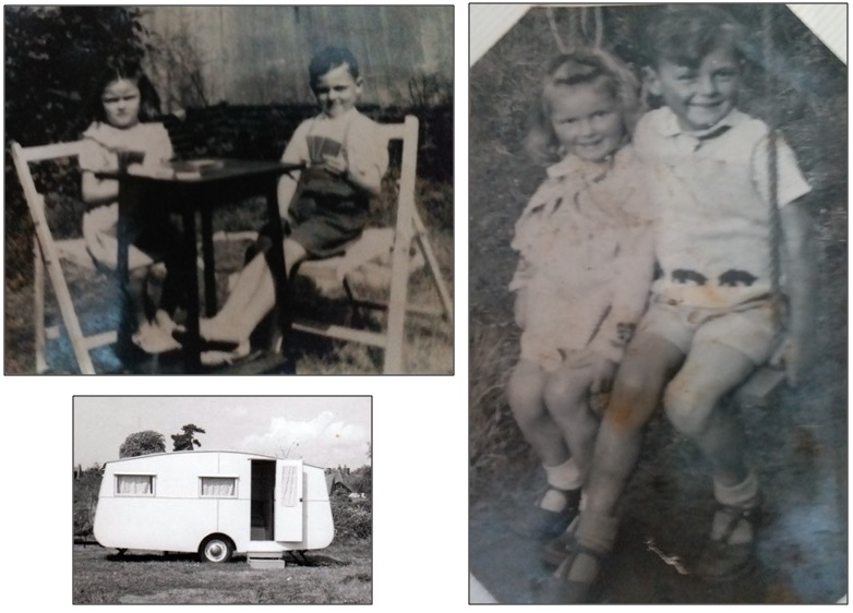
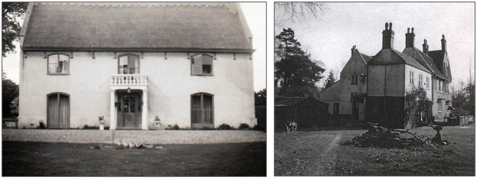
We moved from our very small house to a Cottage next to the Stables in the Manor Grounds, on the left hand side of the gravel driveway going towards the Manor House. My Mother (Mum) used to help and look after Mrs Brooks in the Manor House during the day. This was so much better as we had more room and a garden where we grew vegetables and flowers. My Dad made us a small swing that Audrey and I used a lot. We liked to be in the garden when the weather was good. On one occasion my Granddad and Grandma Onions (Mum’s Parents) came for a Holiday and stayed in a small Caravan near our Cottage. My Dad used to help out at times in the grounds and the maintain the small river leading to Womack. I remember one day my Dad and others were trying to ride a Penny Farthing Bicycle in front of the Manor House which was quite funny.
My sister Audrey and I in our Cottage Garden and similar Caravan in the Manor GroundsThe Manor House Front and Rear
St. Catherine’s Church – Choir
St Catherine’s Church is very large for a small village like Ludham built in the 14th Century but a beautiful example of architecture and construction. My Dad and I were at one time in the Church Choir. My Dad was a very good Tenor and I was a boy Soprano. We used to attend Choir practice together. The Church has 5 Bells and I liked to watch the Bell Ringers before the Sunday Morning Service. I also liked the Harvest Festival Time and Service.
St Catherine’s Church External and part of the Internals including the 15th Century Artwork.
Harvest Time:
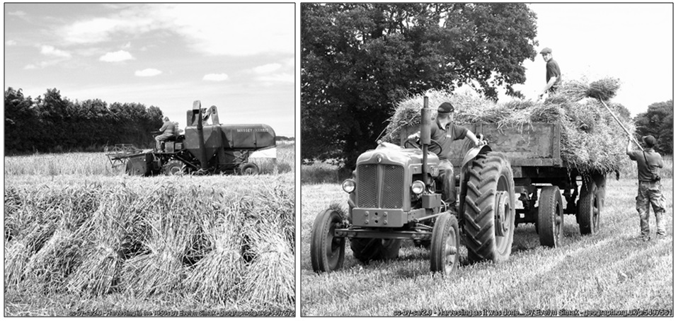
Harvesting was around mid September and the Farmers needed to get their grain harvested as quickly as possible. In the late 1940’s and 1950’s harvesting involved quite a bit of manpower as the Harvester Machines were quite primitive compared to the ones today, so men like my Dad used to help. The boys like Malcolm, Tommy and I would go to the fields being harvested and try to get any Rabbits with our hefty sticks as they ran out of the crop being cut.
Harvesting in the late 1940’s and early 1950’s
My Dad had an allotment on the left hand side of Norwich Road on the way to Rolls Garage. I used to help my Dad as we grew lots of vegetables like Runner Beans, Peas, Cabbage, Cauliflower and Potatoes.
Fishing – My Passion
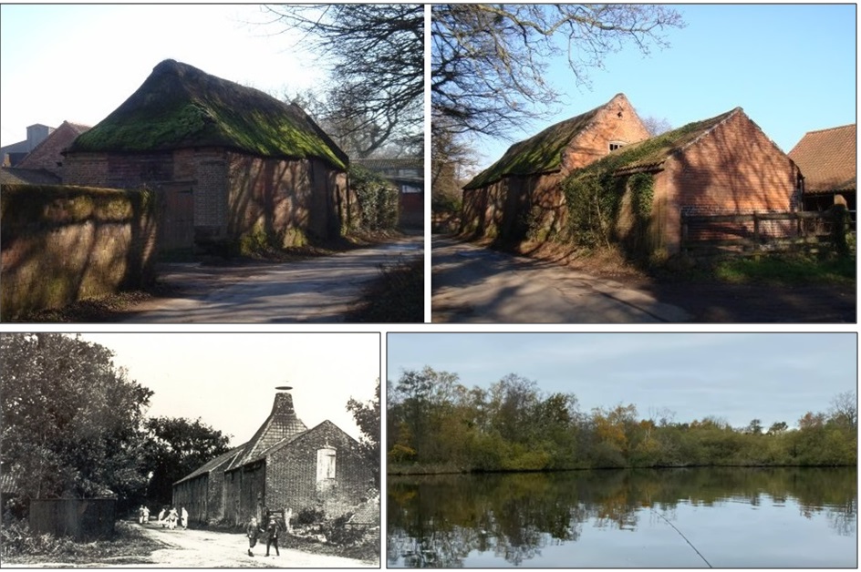
Almost from the day we moved to Ludham in 1946 I wanted to go fishing with my Dad. He taught me how to fish and how to put the tackle together. The nearest place was Womack Staithe as we could walk there from our house. My Dad and I also went to Cold Harbour River Thurne, Hunters Yard and many other places. As I grew older I used to go to Womack by myself at times at 4am before the sun came up passed the Barnes and the Maltings on Horsefen Rd on my bicycle.
The Barnes and Maltings on Horsefen Rd leading to Womack StaitheRiver Thurne near Cold Harbour
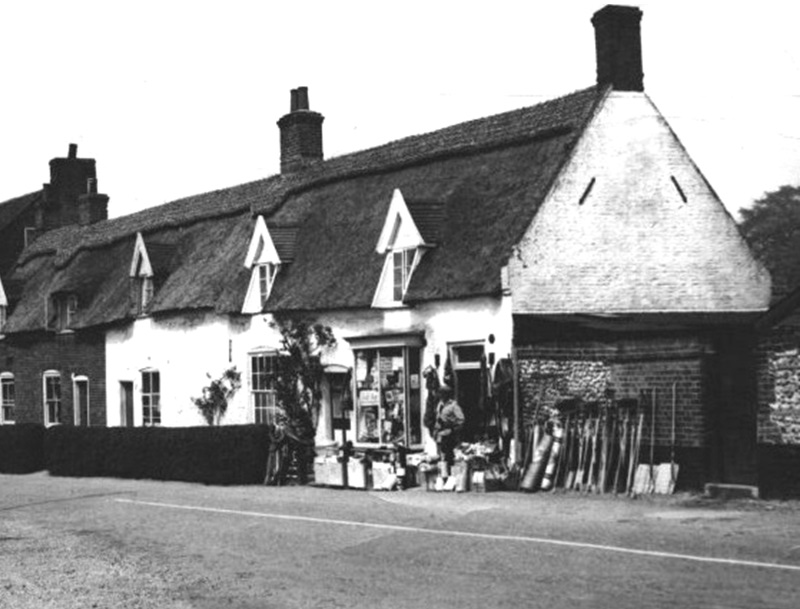
My Dad and I used to get our fishing tackle and rods from the local Albert Knight’s saddlers shop. He was well known for the tall tales he told to tourists but he was very good to the young boys in the village sometimes giving us some fishing hooks and line free. He also used to give us some good advice about where to fish and what sort of fish that were there. We used to catch Bream, Perch, Roach, Eels and other types.
Albert Knight’s Saddlers shop on Norwich Road opposite the Post Office and Church.
Beginning of the end of my first association with Ludham:
In early 1951 my Dad was offered a very good job at a Non Ferrous Foundry in Norwich which he wanted to take. The problem was he had to get a train from Wroxham 7 miles away early in the morning to Norwich and he only had his bicycle. He decided to accept the job in Norwich and he would bike to and from Wroxham every day whatever the weather. That’s what he did for a few months but it was very tiring for him. He decided that the only way was to leave Ludham and move to Norwich. All of us including my Dad loved living in Ludham as our family had many friends but Dad could not continue traveling every day. I was 10 years old and very sad to say goodbye to my friends but we could always pay a visit to Ludham at a later date which we did.
This was our new home in Norwich in 1951. Dad, Mum, Grandma Onions, Audrey and myself
Part 2 – Ludham 1969 – 2005
In 1969 my Mum and Dad decided to move back to Ludham. They were able to move into 5, School Close near the centre of Ludham. I’m sure that made them very happy being amongst old friends again and being back in the countryside and having a garden.
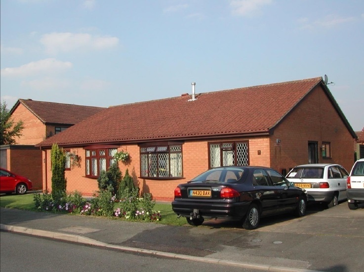
5, School Close Ludham
During the 1970’s
I was married and had a Son called Kevin. We visited Ludham very frequently as I was stationed at RAF Cosford, Shropshire, England, at that time. One of our family traditions was that the guys went for a beer on a Sunday about 12 o’clock and the ladies especially my Mum would cook Sunday dinner with Yorkshire puddings for us returning at about 1.30pm. My Dad and I always went out together at the Kings Arms in Ludham or the Dog Inn near Ludham Bridge or other local pubs near Ludham. We used to play Darts or Dominoes with friends. Although my Dad only had one eye he was still a good Darts player.
The Dog Inn
I was posted to RAF Cosford in April 1969 as a RAF Technical Instructor until May 1975 therefore I was able to visit my Mum and Dad quite often. I believe during this time but I’m not sure of the dates I lived in Ludham with my family for about 12 months at a bungalow Willow Way shown on the image below. This gave me the opportunity to be near Mum and Dad and allowed us to go to many places surrounding Ludham. I remember I had a Lassie Collie dog called Jamie who was about 9 years old in 1975. My Mum and Dad loved Jamie.
Willow Way Bungalow I lived in
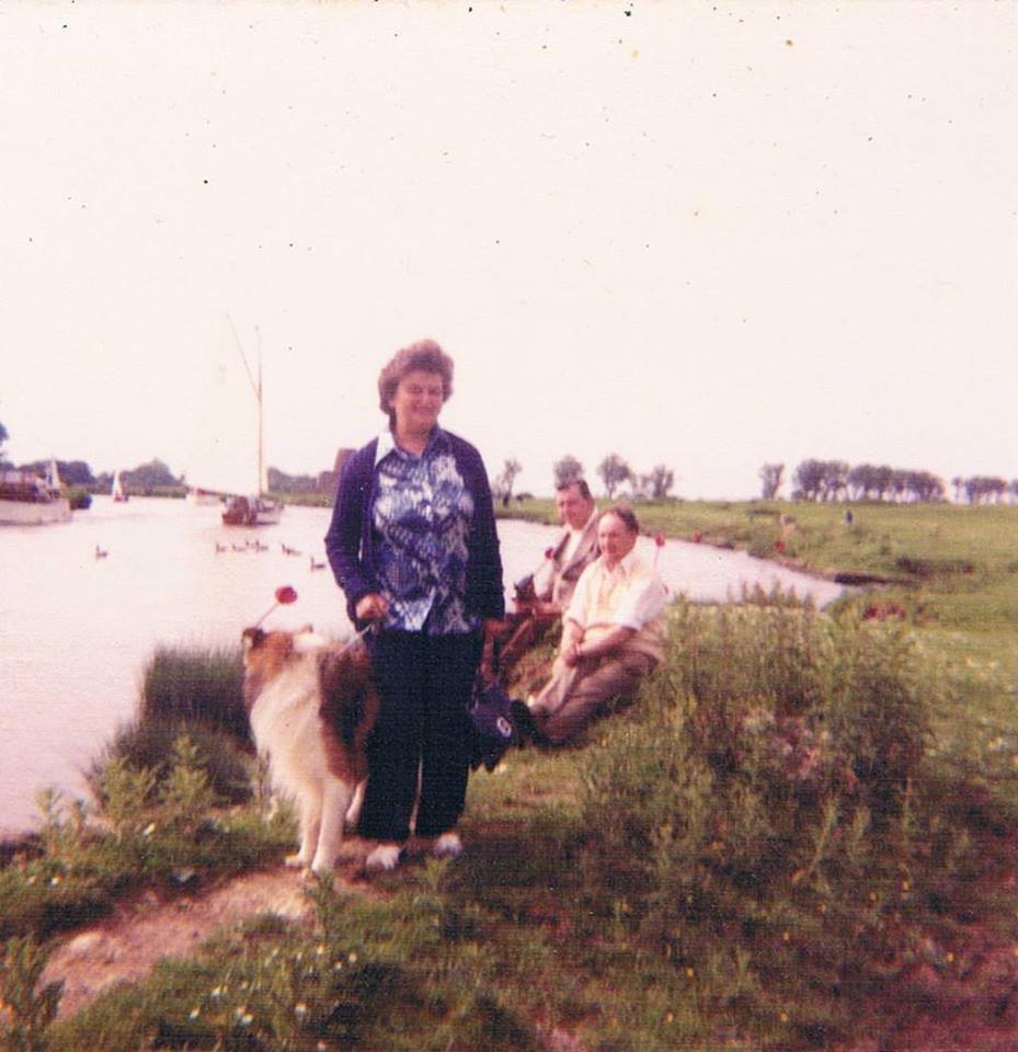
In July 1975 I was posted RAF Wildenwrath West Germany on the Harrier (Jump Jet) Force and my family followed. As Jamie could not go Mum and Dad wanted to look after him. Once again I was outside the country for another 4 years but I did manage to go back to Ludham once or twice during that time. Mum and Dad used to take Jamie to Cold Harbour on occasions. However, sadly Jamie died before I came back to the UK.
Jamie, Mum, Dad and my Uncle Ted at Cold Harbour
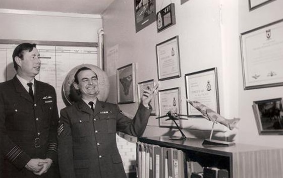
Whilst in RAF Germany in June 1978 with the Harrier Force I was awarded the British Empire Medal (BEM) by Her Majesty The Queen, the highest peace time honour I could be awarded. This made Mum and Dad very happy and on my return to Ludham in July 1979 we had a great celebration.
During the 1980’s
The 1980’s was a momentous period as I was posted to RAF Cottesmore, Tri-National Tornado Training Establishment ( UK, Germany and Italy) (TTTE) in charge of the new Tornado Aircraft Acceptance Team which the RAF received from British Aerospace in July 1980. This was a very busy time for me but we still visited Mum and Dad in Ludham quite often. I was very honoured to receive a certificate from the TTTE Commanders of all three countries. Also in April 1983 I was promoted to Flight Sergeant to take up a new post. Again my Dad and I had a few beers to celebrate on both occasions in and around Ludham.
My new role in April 1983 was to be the Officer-In-Charge of the Harrier Aircraft Ground Servicing School at RAF Wittering. This was a very important position for me but I was still in the UK so our visits to Ludham continued on occasions.
In 1985 I was posted to RAF Laarbruch in West Germany in charge of a large team preparing the Tornado Aircraft in case of war with the USSR which was quite tense at this time. Once again I was abroad and it was difficult to make it back to Ludham to see my Mum and Dad. After a very difficult RAF Germany military exercise in 1986 in which for some reason I was selected to be tested to the maximum for 48 hours non stop with my team, I felt perhaps it was time for a change whilst I was only 45 years old. In July 1986 I resigned from the RAF although I was to be promoted to Warrant Officer and joined British Aerospace in Warton Lancashire. This meant I could visit Ludham more often.
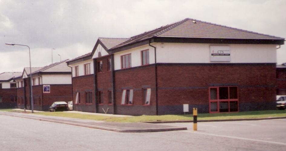
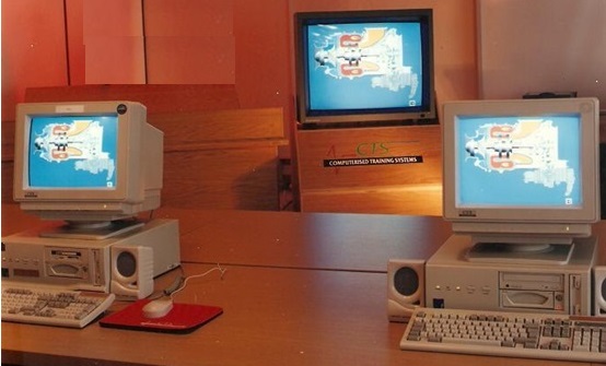
In August 1988 I started my own Company, Computerised Training Systems Ltd (CTS) in Scunthorpe Lincolnshire. The company name was in fact chosen by my Dad as he asked me what we did, I replied Computerised Training, so he said just call it that. This meant I was extremely busy but I still visited Ludham on a regular basis as it was reasonably near. Little did I know the company would last for 33 years.
During the 1990’s
This period was both challenging and stressful but I decided to expand into the Far East and to that end I exhibited at Asian Aerospace 92 which was a great success as I was able to secure a contract with Singapore Airlines and later the Singapore Ministry of Defence. For that reason I spent quite along time traveling back and forth to Singapore. This put a huge strain on my personal life resulting in my wife and I parting. However we both still visited my Mum and Dad in Ludham when we could.
Over the following years CTS expanded both in the UK and Singapore, I therefore decided to split the company CTS in the UK and CTS in Singapore. I therefore lived in Singapore from 1997 on a full time basis.
During the 2000’s
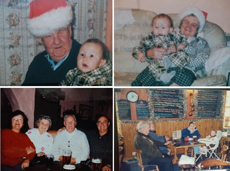
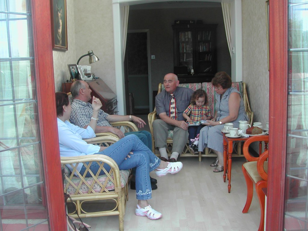
This period was both very happy and very very sad. In 2000 I was married in Singapore to a Malaysian and in late November one month early my daughter Natalie was born. My Mum and Dad were very pleased to be Grandparents again. CTS in Singapore was doing well so we planned to go to Ludham at Christmas 2001 to let Mum and Dad see there 1 year old granddaughter. As it happened it was snowing in Ludham which was nice for Christmas. We met up with the family including my sister Audrey not far from Ludham. We visited Tommy and his wife at their home and went to the Kings Arms. These are some of the images of our visit which was very enjoyable for all of us.
Mum and Dad and sister Audrey and at the Kings Arms December 2001My wife Linda and Daughter Natalie in Ludham and 5 School Close in December 2001My Wife and Natalie with Tommy and his Wife at their home in December 2001
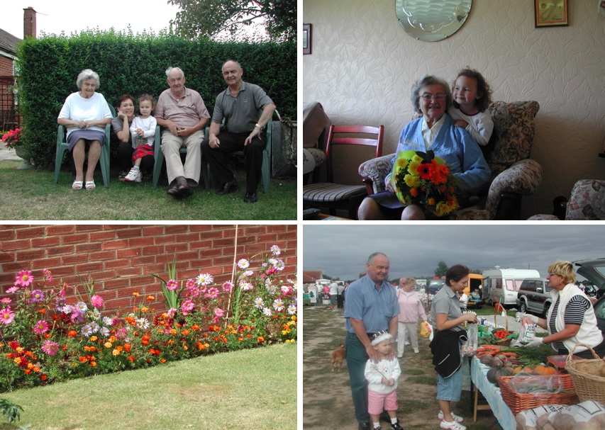
Natalie my daughter was 3 years old now so we decided to go to Ludham to see Mum and Dad in August 2003. My sister in law also joined us. As it happened the weather was very good. These are some of the images of our visit.
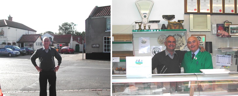
At 5 School Close, Family Group, Mum and Natalie, Dads Flowers and my family at a Market near Ludham 2003Me near Kings Arms and Tommy and Me in his Shop Ludham in August 2003My Sister in Law near the Ludham Sign and The Ferry Inn a favourite place of Dads and mineA Boat Ride from the Swan Inn Horning with Mum and Dad, my Wife Linda and my Daughter Natalie in 2003Meeting Tommy and his Wife in their home in August 2003, Natalie now 3 years old
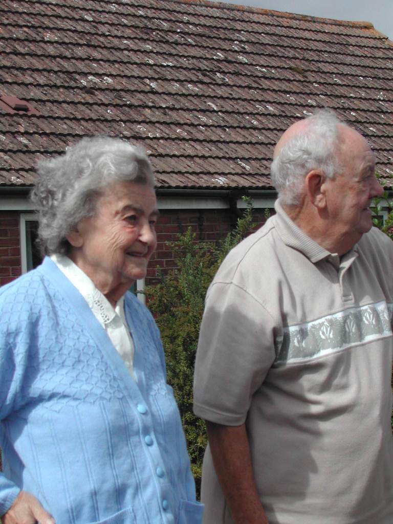
This image was taken as we were leaving 5 School Close Ludham to return to Singapore in 2003. It is very special as it is the last time I will see my Mum and Dad together.
My Wonderful and Loving Mum and Dad and Grand and Great Grand Parents in August 2003
During 2003 the Severe Acute Respiratory Syndrome (SARS) disease broke out in Singapore. After we returned from Ludham to Singapore this had a major impact on my CTS company as all government funds were directed at fighting SARS. As it happened CTS UK wanted to provide me with work initially to do in Singapore. However, a big design task need to be done in the UK in 2004. Then things turned even worse.
SARS in Singapore 2003/2004
I returned to Ludham on the 12th December 2004 as my Mum had a Stroke and was in Hospital in Norwich. On the 23rd December at 5am my Mum passed away. I was with my Dad at 5 School Close Ludham and broke the news to him. He was of course heartbroken as they had been together more than 60 years. Also my wife’s Father passed away in Malaysia only 5 days later on the 28th December 2004, so both of us were very upset.
My Mum who I love and miss so much
I decided to stay in the UK and work with my Son on the UK’s projects. I acquired a small bungalow in Messingham near Scunthorpe as my wife and daughter would join me in February 2005. For the next few months we used to visit my Dad in Ludham but during this time my Dad decided to move from 5 School Close to a Nursing Home near to my Sisters house in Caister On Sea. I returned to Singapore and Malaysia regenerating my company CTS which lasted until December 2021 when I retired aged 80.
Our bungalow in Messingham near Scunthorpe
After this I never went back to Ludham which is always synonymous with my Mum and Dad. My Dad has also passed away but he and my Mum will always be in my thoughts as will Ludham because they are so closely related. Best Wishes to those I knew in Ludham who are still with us.
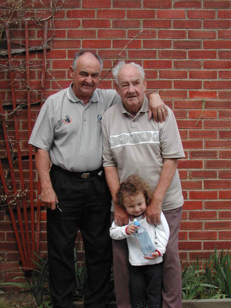
My Dad and my Best Friend who I love and miss so much
I have been very fortunate to have visited many countries in the world including my original home country Great Britain including England, Wales and Scotland. My World Countries I have Visited, first started with my Norwich Technical College Trip to Belgium and France in 1955 when I was 14 years old. I have put the Countries in Alphabetical order.
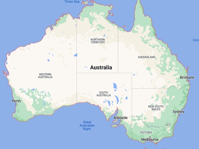
Australia
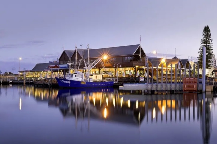
I have traveled from Singapore to Perth twice, many years ago, taking a 4 hour flight, with my Singapore Chinese friends to see my Australian friends and attended the Australian Rules Football game at its stadium. Also went to Freemantle just south of Perth centre which is an oldy worldy sea side type of town with terrific fish and chips and steaks which you cook yourself, plus the beer of course.
Elizabeth Quay Perth Image: Trougnouf (Benoit Brummer)Freemantle Restaurants
Austria
My experience of Austria during the mid 1970’s was mainly the driving from Germany to Venice for summer holidays stopping at places in Austria on the way. There were two routes. The first Munich to Salzburg and then through the Alps on very winding and mostly relatively narrow two way roads to Villach, Udine and Venice. This was towing a caravan which was more dangerous but the scenery was beautiful especially when seeing the mountain lakes with the green/blue water. The second was from Munich to Innsbruck then to Verona which was the latest dual carriageway to Verona and Venice which was much safer but longer. I went both ways on my two holidays in Venice. I notice now the Salzburg to Villach road appears to be dual carriageway.
Alpine Lake
Belgium
Belgium was the first world country I visited with my Norwich Technical College Trip to Belgium and France in 1955 when I was 14 years old. The first place we went to was Blankenberg a sea side town near Knokke-Hiest which my first impression was the smell and taste of Belgium’s black coffee. We then visited Ghent and the Belfry which I still remember climbing the spiral staircase and being defend by the clock bell.
Blankenberg BeachBelfry of Ghent during civil twilight Image: Trougnouf (Benoit Brummer)
Many years later I visited Belgium many times visiting Antwerp, Liege, and Bruges and driving through Belgium on the E40 from England via the Ostend Ferry Port whilst serving in the Royal Air Force in Germany.
Canada
Goose Bay RCAF Base Labrador Newfoundland Canada
The visit to Goose Bay Royal Canadian Air Force Base in Canada was for about 6 hours only whilst we refueled our RAF VC 10 Aircraft on route to the Nellis Air Force Base in Las Vegas Nevada USA. It was heavy snow when we landed and we had to wait until the snow storm stopped before we could take-off for Las Vegas. On the return journey from Las Vegas USA to the UK we stopped again at Goose Bay for a few hours but we had severe turbulence over the USA prior to landing at Goose Bay so it was good to get off the Aircraft although it was still very cold with snow.
RAF VC10 and Goose Bay RCAF Base Labrador Newfoundland Canada
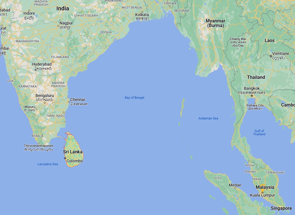
Ceylon (Sri Lanka)
In 1966 whilst traveling from England to Singapore to start my Royal Air Force tour of duty, the RAF Britannia Aircraft had to stop in Columbo the capital city in Ceylon (now Sri Lanka) for fuel. On leaving for Singapore our Aircraft had a bird strike on one of the engines on take-off which forced us to land again. As it was a serious problem which required need spare parts, so we were housed in a high class Heritage style Hotel on the sea front in the south of Ceylon for 5 days. After a frightening time during take-off it was like having a luxurious holiday.
RAF Britannia AircraftA typical Heritage Hotel next to the sea in Ceylon
Denmark
During my time in Royal Air Force Germany we operated some of our Harrier Aircraft from a Denmark Air Force base north of Esbjerg for a period of time. We drove there and back as a convoy from Germany to Denmark taking all of our support equipment. This was in early spring so it was quite cold but the Denmark Air Force personnel were very friendly.
Harrier Aircraft of my 20 Squadron RAF Germany
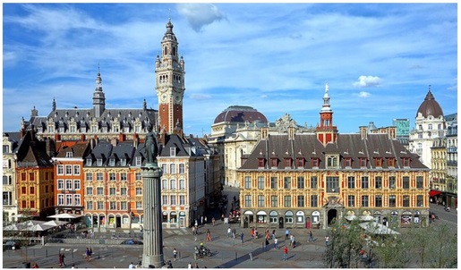
France
The first time I visited France was on my Norwich Technical College Trip to Belgium and France in 1955 when I was 14 years old and visited Lille not far from Ghent in Belgium. I flew to United Airlines HQ in San Fransisco using Air France from Paris in 1989 two weeks after the San Fransisco earthquake. I remember the Air France male flight attendants were not very helpful at all during the flight and refused to speak English. In the early 1990’s I visited Paris and Disney Paris with some friends for a few days seeing the Eiffel Tower and River Seine. Also in the mid 1990’s I drove my BMW 750i from Calais to Swissair, Basel in Switzerland via Reims and Belfort through many Tunnels with my staff for a Training Presentation to the European Union Aviation Safety Agency (EASA), and world Airline Executives for a few days which took 11 hours there and 11 hours back at one time reaching 130mph only stopping for food and fuel. Although a long drive it was very enjoyable seeing all the different scenery.
Clock Tower of the City Hall Lille FranceParis – France Eiffel Tower and River Seine Image: Yan Caradec
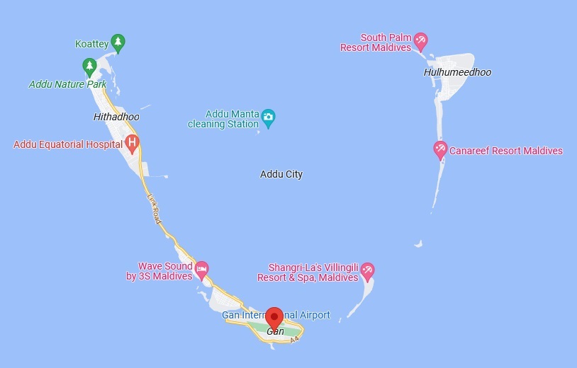
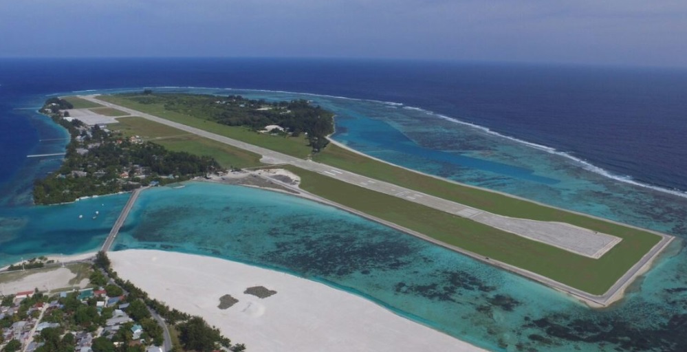
Gan (Maldives)
In 1966 Gan in the Indian Ocean was a Royal Air Force (RAF) Airfield and Base. Its Aircraft Runway stretches almost the whole length of the Island. I was allocated to a VC10 Hospital Flight on my way back from RAF Singapore to England which had to stop for 5 days for the patients on board who were moved to the Gan RAF Hospital for treatment. This gave me and my colleagues chance to enjoy diving off the Pier and swimming in the beautiful clear waters with all the colourful fish just like a holiday. The VC10 just managed to take off at the end of the Runway very close to the sea. Today Gan is part of the civilian Maldives holiday complex.
Gan’s Aircraft RunwayA VC10 Taking Off from Gan in 1966
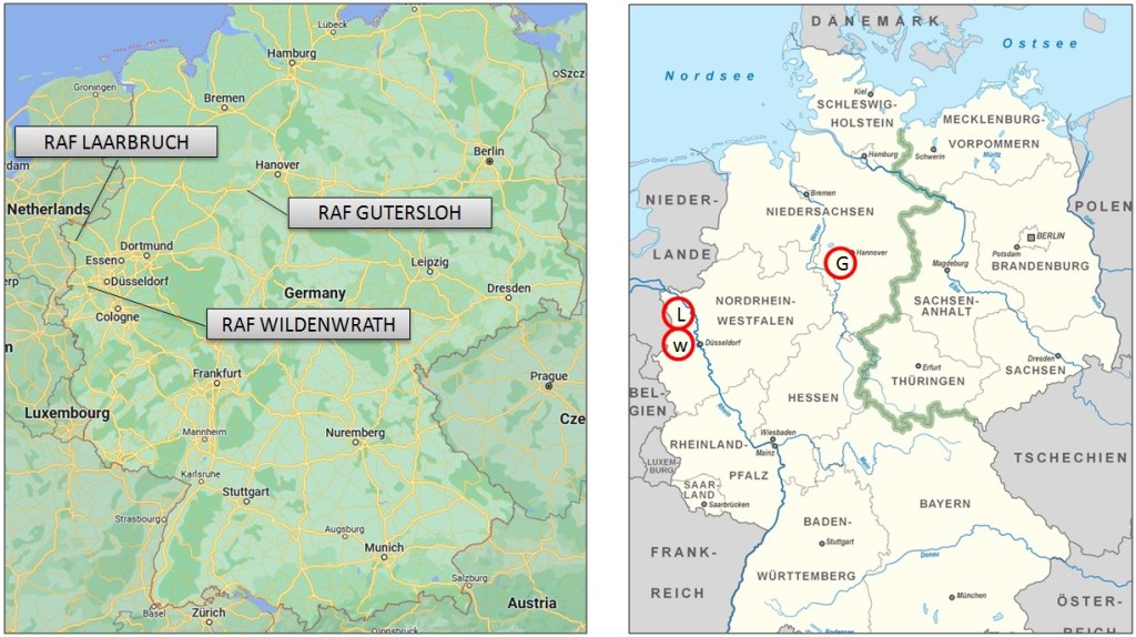
Germany (West)
Germany was separated West and East from 1949 to 1990
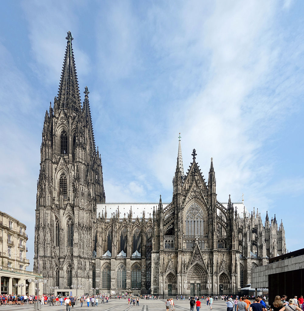
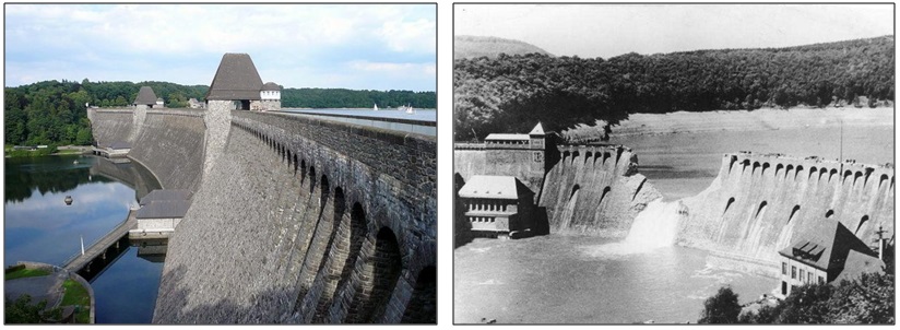
I was posted to Royal Air Force (RAF) Harrier Aircraft 20 Sqd Wildenwrath in 1976 and then to RAF Harrier Aircraft 4 Sqn Gutersloh which was nearer the East German border in 1977 until 1979. This was a very tense period with the Cold War between NATO (West Germany) and the Soviet Union controlling (East Germany). In early1985 I was posted to RAF Tornado Aircraft 20 Sqn Laarbruch until my RAF retirement late in 1986. I visited, driving on the German Autobahns that has no speed limit, to many places in West Germany from Hamburg in the North to Munich in the South such as Cologne and its beautiful Cathedral. The other significant part of Germany is the mighty River Rhine which is used for Commercial Barges and Tourist Boats which I have been on. It originates in Switzerland flowing through the whole of Germany and ends in the Netherlands. I also visited the Mohne Dam which was breached during WW2 by the RAF famously known as the ‘Dambusters’ using the ‘Barnes Wallis Bouncing Bomb’. However it was back to original glory when I visited it.
Cologne Cathedral Image: VelvetRiver Rhine Image: Holger WeinandtLeft: Mohne Before and After the War Right: During WW2 RAF Dambusters Breached the Mohne Dam
Hong Kong
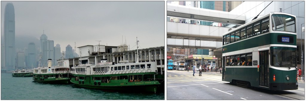
Most of my visits to Hong Kong have been before China took it over. I visited on business talking to the Hong Kong and world movie companies and the other times on holiday. I also visited Macau only a short boat ride from Hong Kong. I have always enjoyed being in Hong Kong with its Ferries, Trams and bustling population.
Hong Kong Ferries Image: Dudva and Millennium Tram Image: Mk2010
Indonesia
Indonesia a country of extremes and is a huge area made up of many islands many of which are not shown in the map. The areas that I have been to are shown in the circles. Jakarta the capital and Bandung were two places I visited for business trips for a Training Contract which I eventually terminated with an Indonesian Aircraft Manufacturer based in Bandung in the 1990’s developing the N250 Aircraft. Bandung City is a place of two halves, the very rich who live in very expensive large houses away from the city centre and the very poor who live in a shanty town environment. I used to fly from Singapore to Bandung in a Merpati Airlines old Fokker 90 Aircraft which I did not like as they were very old.
The N250 Aircraft and the Merpati Fokker 90 Aircraft
Bintan is a small Indonesian island just off Singapore that the Nirwana Resort Hotel shown in the image below has a very special place in my heart for personal reasons some 24 years ago and is a super holiday place. Bali which I have been several times long ago is also a very good holiday place having beautiful beaches with Balinese Dancers in their traditional dress that perform typical dances of Bali. I enjoyed being on the Jet Skies as the water can be quite wavy and going on a large Catamaran Boat to another Island to see the Coral and Snorkeling.
Top Left Bintan Nirwana Resort Hotel: Top Right Balinese Dancers and Bottom: Bandung City
Italy
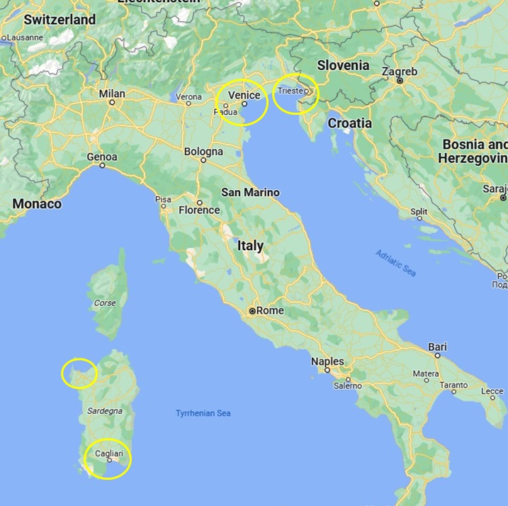
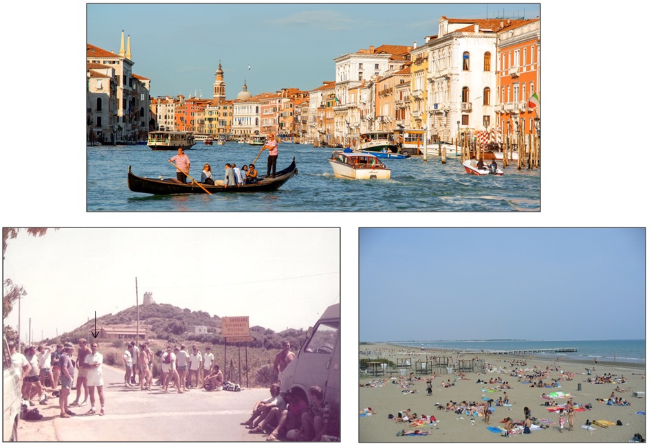
I had two distinct reasons for going to Italy. The First was with the Royal Air Force (RAF) where we went to the Island of Sardinia (Sardegne) near Cagliari for exercises. At weekends I (arrow) would take my team to the north of the Island where we relaxed in our camp site near the beautiful beaches. The second was on two holidays trips to Venice driving from Germany through the Alps and Austria via Salzburg and Innsbruck and parking my caravan near the Venice beach and then visiting Venice itself. Venice is a very unique place where the ‘streets’ between the buildings are in fact small waterways where the ‘Gondolas’ small boats, shown in the image below, taking people and tourists from one place to another. I also took the opportunity to visit the beautiful port city of Trieste not far from Venice.
Top Image: Leandro Neumann Ciuffe Bottom Right Image: Peter K BurianTrieste Image: Nick Savchenko from Kiev Ukraine
Kuwait
On my way to Singapore on the same Royal Air Force (RAF) Britannia Aircraft shown in the Ceylon part, we had to stop for refueling at Kuwait. This was a very unpleasant experience as we had to get off the Aircraft and were all, about 100 of us, put in a small room ,no air conditioning, no refreshments for about 6 hours. We were not allowed to leave the room as there were armed guards outside. I was very pleased when we left for Ceylon.
Laos
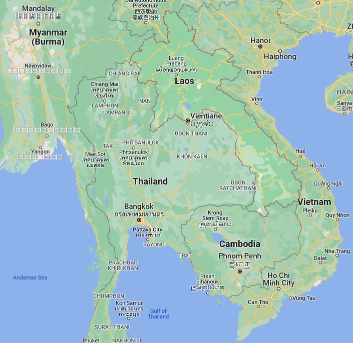
I visited Laos for a few hours whilst at the Golden Triangle at Chiang Rai in Thailand. This is where Laos, Myanmar ( Burma) and Thailand all meet in the middle of the Mekong River. I went across the mighty Mekong River in a small boat to the Tourist Market in Laos. It was important not to stray into the Myanmar part of the river as it was banned. I also went to the Golden Triangle Arch which is in Thailand but you can see Laos on the other side of the river.
Luxembourg
I visited Luxembourg whilst I was stationed at RAF Wildenwrath in Germany for a couple of days. It is surrounded by Belgium, France and Germany and is a very beautiful small country with many old buildings.
Luxembourg City Image: Cayambe
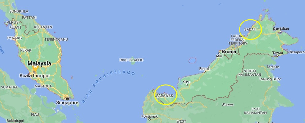
Malaysia
Malaysia has been my home for the past 18 years, however I was first in Malaysia in Feb 1966 with the Royal Air Force at RAF Butterworth in North Malaysia. Malaysia consists of three countries, Sabah, Sarawak and the Malay Peninsular States with the capital Kuala Lumpur. I have visited many places in the Peninsular, like Penang, Malacca, Johor and surrounding Islands such as Redang Island which have beautiful beaches. My home is in the state of Selangor which is near to Kuala Lumpur and is generally a very nice country with a multicultural people who are generally also very nice, as long as you don’t get involved with politics and religion. Malaysia is famous for it Petronas Twin Towers, its production of Palm Oil and Holiday destinations throughout Malaysia and its surrounding Islands.
Redang Island Malaysia Image: Mukherjeesaikat
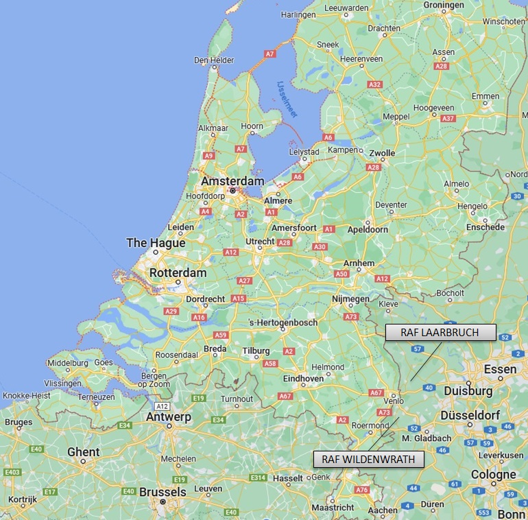
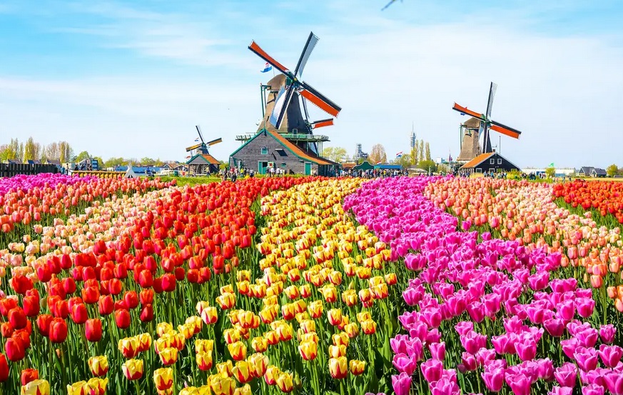
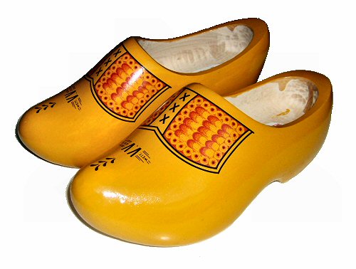
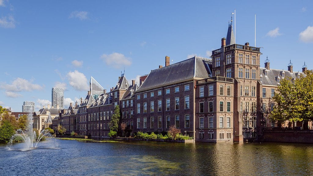
Netherlands
The Netherlands also known as Holland is one of the World Countries I have visited the most living outside of the country. There are two main reasons. The first is that whilst in the Royal Air Force (RAF) stationed at RAF Wildenwrath and RAF Laarbruch I used to go shopping very often to Venlo and Roermond as it was cheaper than Germany and it was nice to have a day out. Also, I used to go out for day trips to places like Eindhoven, Maastricht, Aachen, Nijmegan and Arnhem. The second was having holidays and business trips to Amsterdam, The Hague and Rotterdam where the Ferry from Hull in England used to dock. Also I used to fly from Singapore to England via Amsterdam Schipol Airport where I changed Aircraft. The Dutch (Netherlands) people are very friendly and most speak English. Holland is very famous for their Tulip flower Fields, Windmills and their Wooden Clogs (Shoes). Overall its one of the best places I have visited.
Singapore has been a significant place for me for many reasons. In February 1966 I arrived at RAF Changi and the moved to RAF Seletar to rebuild 4 Jet Provost Aircraft to help with the Malaysian/Indonesian confrontation which ended on the 12 August 1966. Singapore gained its Independence on the 9 August 1966. In December 1966 I was posted to RAF Seletar Electrical / Instrument unit for 3 years. I lived in Seletar Hills near RAF Seletar. In those days Singapore was a very different oldy worldly place, such as Jalan Kayu the nearest village to the RAF Seletar Base and Seletar Hills.
Jalan Kayu Singapore 1967 Image: jalankayutrail.blogspot.com
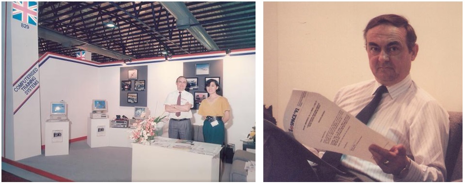
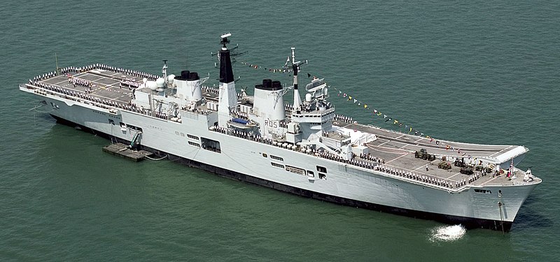
I returned to Singapore in 1990 and the in 1992 for the Asian Aerospace Exhibitions as Managing Director of my own company CTS. In addition in 1992 I was invited to give a demonstration of our Training software to the Chief of the Singapore Navy, on board the Aircraft carrier HMS Invincible which was docked in Singapore as part of Orient 92. I would meet him several more times as a Singapore Minister of Defence and Education when I opened my my Singapore company in 1993. This generated new business with Singapore Airlines, Civil Aviation Authority of Singapore and the Singapore Ministry Of Defence that meant I needed to visit Singapore almost every two weeks from the UK. For personal reasons I then decided to live in Singapore in the mid 1990’s until 2003.
Asian Aerospace 1992 Me and My Company CTS exhibition standHMS Invincible
I was at Orchard Road for the 2000 New Celebrations with another 500 thousand of people. In March 2003 the virus SARS broke out in Singapore forcing me to close my Singapore company and move back to the UK for a short while. Singapore was very different to the 1960’s with modern buildings everywhere you looked but also preserved heritage sites. Today RAF Changi and RAF Seletar are civilian Airports with Changi being one the biggest and one of the best Airports in the world.
Orchard Road New Years Eve 1999-2000
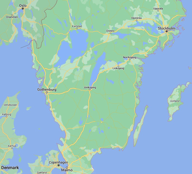
Sweden
Southern Sweden
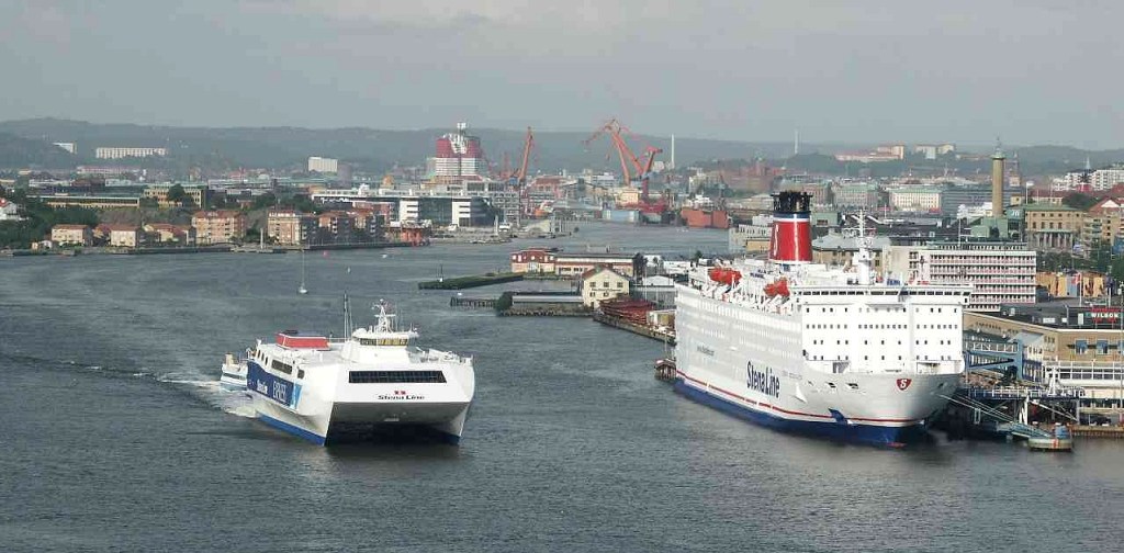
I visited Sweden in the winter of 1989 to acquire work from SAAB the Car and Aircraft company based in Linkoping and Stockholm. I decided to drive using my brand new BMW 518i by using North Sea Ferries from Hull in the UK to Gothenburg in Sweden. When I arrived in Gothenburg at 1am after a very long and rough sea journey, it was freezing and I was lucky to see some Taxis one of which helped me find my hotel.
Gothenburg Port and Ferries
The next day I drove to Linkoping although it had been snowing and the temperature was well below freezing. However, the scenery on the way was very beautiful and I stopped at some small Cafe’s on the way. The Swedish people were very friendly and spoke English very well as its their second language. I eventually reached Linkoping and the next day visited the SAAB factory for my meeting.
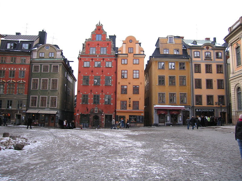
The next day I left Linkoping and drove to Stockholm the capital of Sweden for another meeting with SAAB. Again the weather was very cold with snow flurries on the way but reaching Stockholm it was very busy. My meeting was the following day so I had chance to see a small part of Stockholm. Although SAAB showed a lot of interest in CTS and our Training Systems and Software, it was so new that they were hesitant to accept this completely new approach to training. After the meetings I then drove back to Gothenburg from Stockholm that took me about 8 hours through this beautiful country which I enjoyed very much for the few days I was there.
Part of Stockholm in winter with their unique housing designs
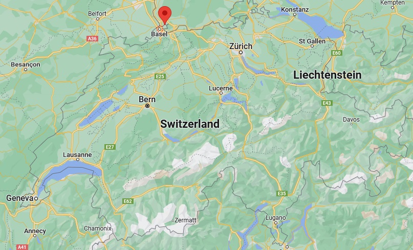
Switzerland
I visited Basel in Switzerland for a Presentation to the European Union Aviation Safety Agency (EASA), and about 300 World Airline Executives regarding the Computerisation of Training for the EASA Part 66 Aircraft Maintenance Engineers for world wide use, hosted by Swissair. As I have said it took me about 11 hours from my office in Scunthorpe via the Channel Tunnel and France to Basel by my BMW 750iL car shown below with my own number plate. ‘Hogg for CTS’ which was my company.
Arrived at Swissair Switzerland in my BMW 750iL
My team and I stayed for a few days in Basel during the Summer before and after the Presentation discussing the EASA Part 66 Computerised Training aspects, costs and development time. It was clear that after the Presentation the Airline Executives were concerned regarding these aspects but were pleased that these were highlighted by me as they thought this would be a very easy and quick thing to do. It was decide much later that the Airlines would make their own arrangements for EASA Training. Basel was a very nice place with many shops and places outside Cafes and Bars and very friendly people. It also has a very comprehensive Tram System to allow people to get around without having to have a car as they were banned from parts of the city centre.
Parts of Basel City Centre during the Summer with outside Cafes, Bars and lots of Trams
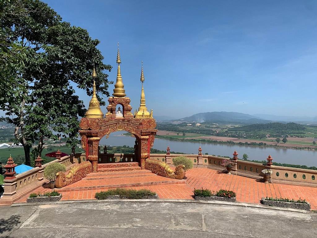
Thailand
Left: North Thailand Right: South Thailand Bangkok: Capital of Thailand
Thailand is one of places I have visited the most due to proximity to Malaysia and ease of access. Visits have been for holidays only on the beautiful beaches and surrounding Islands and for shopping and sight seeing. One of my favourite places in Thailand is Krabi in southern Thailand. I remember some years ago we stayed at the Railay Beach Resort and Spa for Christmas which is a collection of individual cottages and has entrances from Railay Beach and Pool and from the rear Pool and Beach. The sun set is stunning and the beach and sea are idyllic.
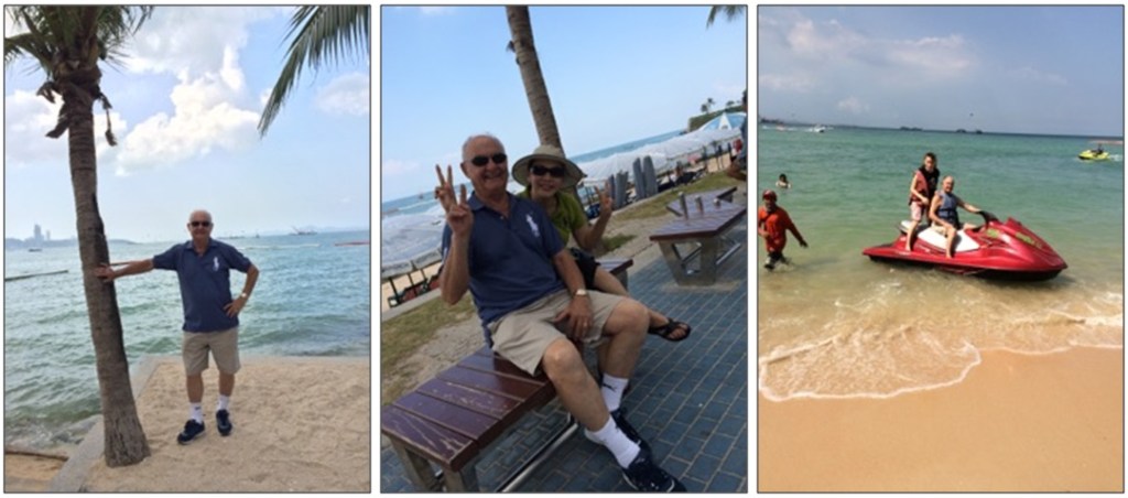
We have also visited Pattaya City south of Bangkok which also has a very beautiful Beach and other attractions as most sea side towns have.
My wife, daughter and me at Pattaya Beach
One of the best Thailand Islands (Koh) I have been to is Koh Lipe a small Island in the South Andaman Sea. To get there we took a flight to Langkawi Island part Malaysia and through customs to the Thailand part. Then a ferry from the Thailand part to Koh Lipe by a large Ferry which takes about 2 hours. We stayed on Koh Lipe for a few days going out to even smaller islands by Speed Boat. There are also smaller boats called ‘Long Tailed Boats’. The reason is that the engine drives a propeller through a ‘long’ shaft. The waters around Koh Lipe and the other Islands are so clear and green / blue with white sand its just so beautiful and well worth the journey to get there.
Koh Lipe in the South Andaman Sea ThailandLeft: Long Tail Boat Right: Speed Boat
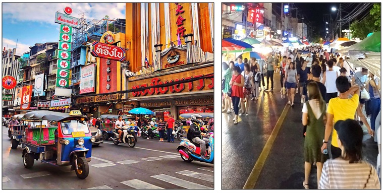
Bangkok the capital of Thailand is a bustling city with many places to see but many people go for the large shopping centres where you can spend a whole day buying almost anything you want especially clothing. Chiang Mai is a much smaller city with many types of Temples and is an oldy worldy place with a character of its own. The night markets are a special attraction for locals and tourists.
Left: A Bangkok Main Street Right: Chiang Mai Night Market
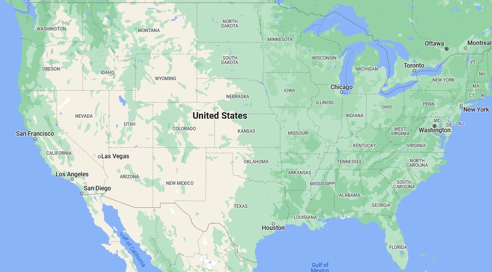
United States of America
I have visited the United States of America (USA) twice. The first time was in 1985 with the Royal Air Force when we were attached to the Tactical Air Command at the Nellis US Air Force Base Nevada only a short distance from Las Vegas. We arrived from Canada in our RAF VC 10 Aircraft. I was in charge of my team and responsible for final ‘pre-take-off’ clearance of our Tornado Aircraft. As such I had access to a car and Oldsmobile the same style and colour as the image below which allowed me and my senior team members to travel around during our long weekend off duty.
During our off duty time we visited the Hoover Dam in Nevada and then drove through the Nevada Dessert to Disneyland and Universal Studios in Los Angeles which was extremely busy and then to Sea World in San Diego. From San Diego we traveled back to Las Vegas to the casino Hotel we were living in. Were were in Las Vegas for 5 weeks which became quite boring. We then flew back to the UK via Canada in our RAF VC 10 Aircraft.
Sea World, Universal Studios, Disneyland and the Hoover Dam
The second time was in November 1989 only 2 weeks after the Loma Prieta 7.2 Magnitude Earthquake in California including San Francisco. Many of the Highways had collapsed on top of each other. I had already arranged a meeting as Managing Director of my own company Computerised Training Systems Ltd (CTS) with United Airlines in San Francisco. This was to discuss the possibility of creating their Maintenance Training software. After the meetings I had some spare time and some of the United Airlines guys showed me around San Francisco and the famous Golden Gate Bridge. They also took me to a restaurant / bar way up a very high hill overlooking San Francisco Bay area. Overall at that time it was very enjoyable and a unique experience on both my visits to the USA.
United Airlines and the Golden Gate Bridge
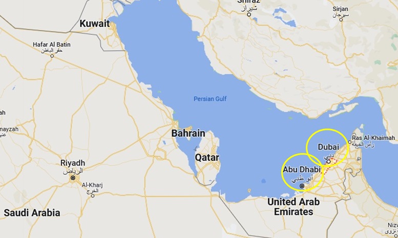
United Arab Emirates
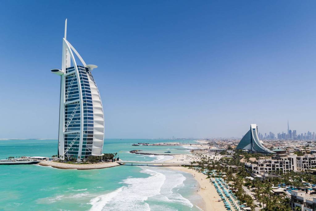
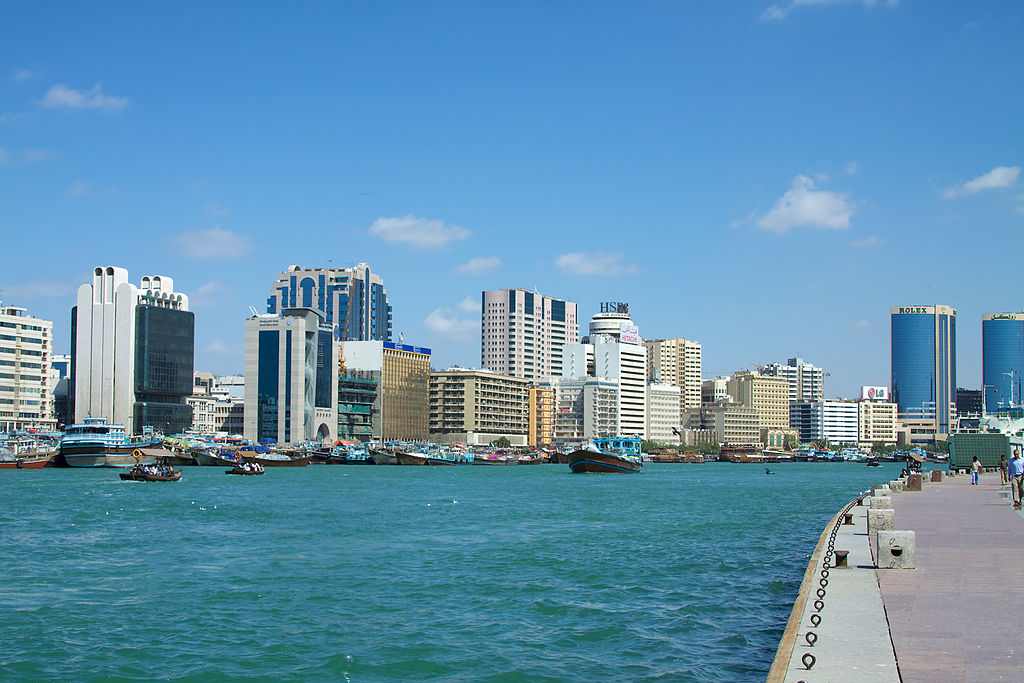
I have visited the United Arab Emirates several times for business and pleasure. In 1993 I had a contract with GEC Marconi to develop Computerised Training for their In Flight Entertainment System installed on Emirates Airlines (EA) Aircraft which is based in Dubai. Therefore I worked with the EA Cabin Crew which involved me going to Dubai on a regular basis. I stayed at the Jumeirah Beach Hotel which is shaped like a wave (right). The beach and facilities were fantastic. Whilst there in 1993 I saw the Burj-al-Arab (left) being built. Dubai City was a bustling place with very beautiful high rise buildings near the major river.
Left: Burj-al-Arab Right: Jumeirah Beach HotelDubai Centre near the River
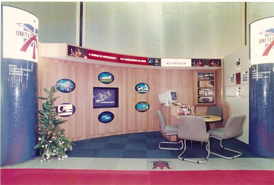
Still on the business part I exhibited my company CTS at the Dubai Air Show in 1995 as CTS was now known in this area. I had this CTS Stand especially built in the UK which was modular for transportation, that was used in Dubai and other exhibitions around the world. In addition I had meetings in Abu Dhabi another beautiful City in the UAE.
Computerised Training Systems Ltd (CTS) Stand Dubai Air Show 1995Me at the CTS Stand Dubai Air Show 1995
On a private visit I stayed at a Small Beach Resort which is no longer there but was very relaxing away from the glitz of Dubai City and High End Hotels that I have stayed. Overall Dubai at that time was affordable and less commercialised, however today it has expanded into a rich mans destination as it is a stunning place.
Vietnam
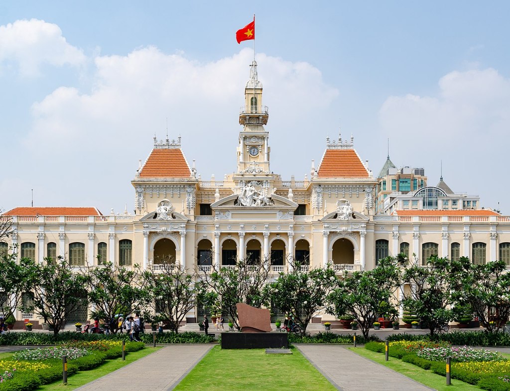
South Vietnam; Ho Chi Minh City
I visited Ho Chi Minh City in South Vietnam once with my Chinese friends. It is a bustling city with an enormous amount of Motorcycles. This is the preferred for of road transport but the shear number and the way there seems to be no rules for movement is amazing. The problem is walking across the road, you simply have to walk into the traffic and the traffic will go around you but its frightening the first time you do it.
This impressive building is the City Hall which overlooks a huge Square in the middle of Ho Chi Minh City that attracts a lot of tourists. The famous ‘banh mi thit nuong’ is a crusty bread roll withe items inside which is also known as a Portuguese Bread Roll. The Bread is fantastic!!
Conclusion
Thank you for looking at this long post and I hope you found it interesting. There are so many places in some countries I have visited which have not included as I have been so lucky to have traveled the world in my life experiences.
Today there is so much talk and concern that we the Humans are Destroying the Planet Earth due to our activities. However, we should remember that our Planet has been here for at least 4 billion years and has survived every adverse occurrence since its creation. The question should be ‘Will the Humans destroy themselves not the Planet’?
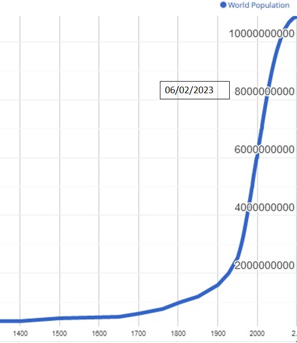
In the year 1400 the Planets Human Population was estimated to be 550 million (550,000,000). In only 650 years from the year 1400, (2050) it is estimated that the Planet Human Population will be 10 Billion (10,000,000,000). 650 years compared to 4 billion years is only a minute fraction of time (0.0000001625) years that a major amount of Humans have been on the Planet. The present Planets Human Population is said to be 8 Billion and rising rapidly.
The Increase in the Population is exponential as in 1950 to 2050 the Population will have increased from 2 Billion to 10 Billion in just 100 years. In the next 100 years the increase rate could be even higher with humans living longer and child birth higher due to medical advancements and increased living standards.
The problem is how long can the Planet Resources sustain the rapid exponential increases in the number of Humans and what effect will this have on Human to Human interface.
Human Industrilisation
Looking at the Planet Population Graph the start of the exponential increase in Population is related to the start and exponential growth of the Human Industrialisation around the 1750’s.
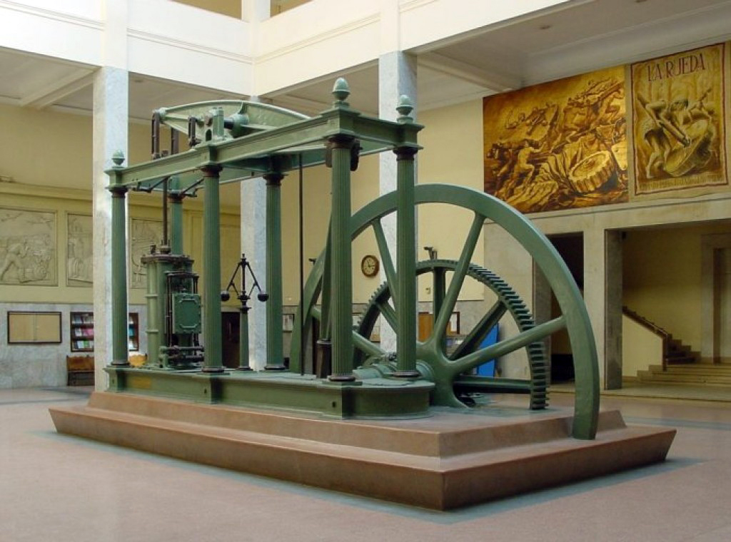
The Steam Engine:
The invention of the James Watt Steam Engine a Scotsman in 1769 was a very significant turning point for the Planet.
The Steam Engine Power principles were improved and adapted over the next 50 years to other Machines for Manufacturing, Pumping and Transportation such as the ‘Rocket’ Steam Locomotive in 1829 in England. The Steam was produced in a Boiler heating water using Coal. However Coal produces Carbon Dioxide CO2 which was emitted into the atmosphere. As other countries including the United States and Europe followed England’s lead so the CO2 emissions dramatically increased further.
The Electric Motor, Generator and Lights:
The invention of Magnetic Induction, Electrical Motor and Generator by England’s Michael Faraday in 1827 and the Light Bulbs by the USA’s Edison and Tesla in the 1870’s together with many others began another significant turning point on the Planet, Electrical Power. However, to produce the Electrical Supply, Power Stations were constructed which had Generators driven at first with Steam using Coal and then additionally Gas. These also produce a significant amount of CO2 emissions. 37% of the Planets Power Stations use Coal.
The Internal Combustion Engine:
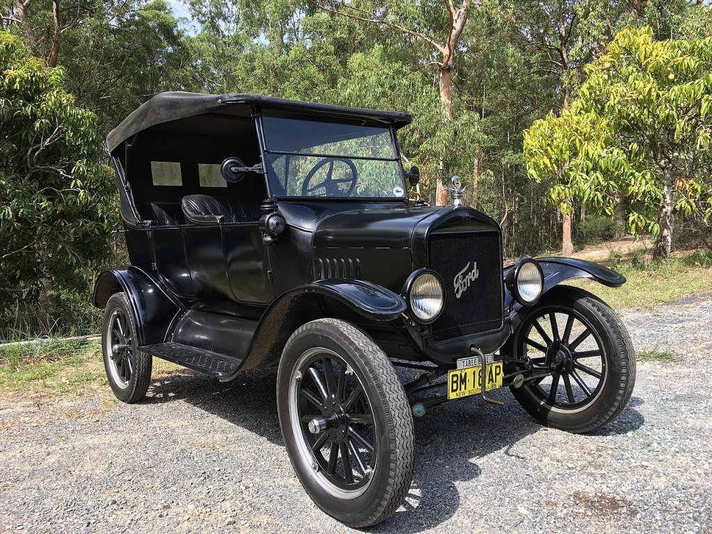
The first modern Internal Combustion Engine, known as the Otto engine, was created in 1876 by Nicolaus Otto. With the introduction of the mass produced Ford Model T motor car in 1903 the road vehicles have transformed the Humans life worldwide but they have had a major impact on the amount of CO2 emissions due to the use of Oil and Natural Gas for their internal combustion engines. There are estimated to be 1.4 Billion road vehicles, cars, trucks and buses in the world today plus about 500 million motor cycles.
Aviation the Jet Age:
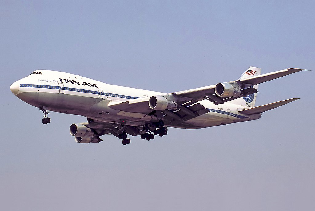
Since the invention of the Turbo-Jet Engine operated in 1937 by the Englishman Frank Whittle and the first Commercial Jet Airliner the English de Havilland Comet in 1949 the Aviation industry has expanded significantly. This expansion increased significantly with the introduction of the Boeing B737 in 1967 and the Boeing B747 ‘Jumbo Jet’ in 1970 to Pan-Am. This also contributes the amount of CO2emissions.
Climate Change due to Human Interference
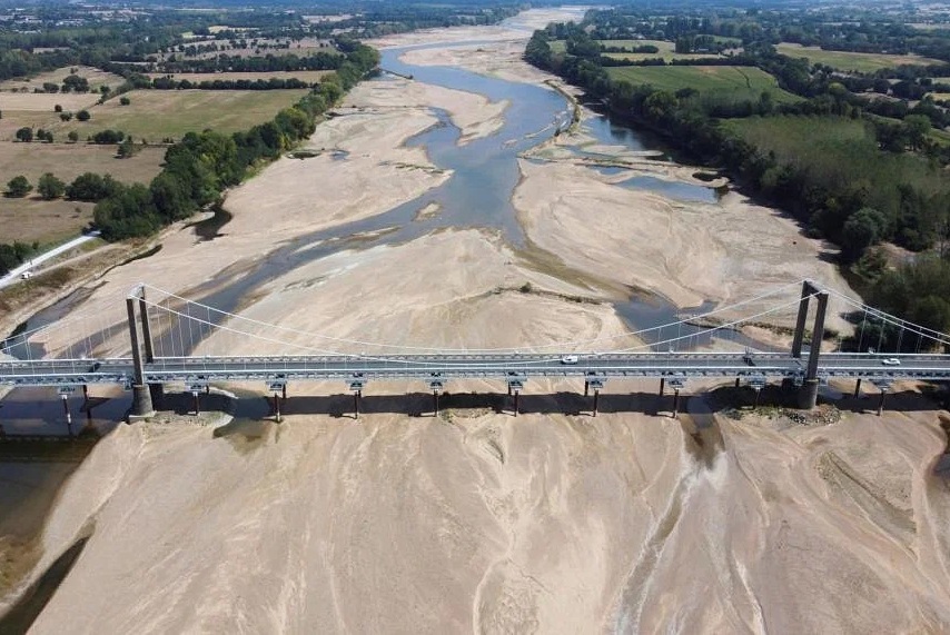
It has been scientifically proven that the ever increasing CO2 is a major factor in what we know as ‘Climate Change’. This actually means we are effecting the Planets ‘Natural Climate Cycle’ that has been ongoing for Billions of years without major Human Interference. This has changed significantly since the mid 1750’s Industrial Revolution and Population Increases as we have seen. This has resulted in increased Strengths in Hurricanes, Typhoons, Droughts, River and Reservoir Levels, Floods and Seasonal Changes all over the Planet. The North and South Poles and Countries are experiencing the melting of the Glaziers and Ice Sheets due to higher overall Planet Temperatures. It is estimated that 65% of the Planets Glaziers will have melted away by 2100. Much of the Mountain Ice provides ‘Fresh Water’ essential for all Life and Vegetation on land.
Loire River France February 2023 caused by drought conditions Image: Reuters
The Planets Diminishing Resources for Life on Land
The two most important Planet Resources for Life is ‘Fresh Water’ and ‘Food’. Without either of these Resources Life on Land will cease.
We have heard the saying ‘Supply and Demand’. The Supply of ‘Fresh Water’ and ‘Food’ is decreasing whilst the Demand from Humans ‘Fresh Water’ and ‘Food’ is increasing rapidly. Conclusion: Humans will die from ‘Thirst and Hunger’ as some are already doing so in parts of the world.
AusAID/Jim Holmes
If the Humans cannot solve this problem there will be major conflicts between Humans for ‘Fresh Water’ and ‘Food’ as the Population continues to Increase ‘Fighting to Live’.
Humans must also consider although there will be Rainfall producing ‘Fresh Water’ nature itself including the Forests, Vegetation, Insects and Wild Animals that are still living will consume a bigger percentage of the ‘Fresh Water’ before it reaches the Rivers, Lakes and Reservoirs for Humans. Due to Climate Change Rainfall itself is unpredictable and contaminated by increasing Air Pollution.
Human Efforts to Address the Resource Problem.
Fresh Water:
Although Humans have developed some Desalination Plants (Sea Water to Fresh Water) mainly in the Middle East and parts of Africa these produce a minimal amount of Fresh Water and consume a great deal of Power heating the sea water. Generating that Power will at present create more CO2. Other chemical orientated methods are being investigated but can these solutions produce water in volume that will be needed for the human race.
Food:
Farming is becoming more automated using new technology like Electric Autonomous Driverless Tractors (image) and Harvesting Machines. Farming Techniques are advancing and Water Conservation and Irrigation are improving Food Production. However, more Food means more Land required to grow it which is leading to Deforestation which is reducing the absorption of CO2 by the Trees and erosion of the soil.
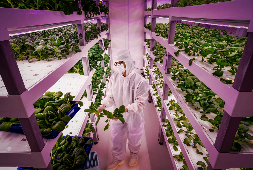
Indoor farming is increasing which use much less water and creates photosynthesis lighting effect to feed the plants. However, this technology is minute in comparison to traditional farming.
Indoor Farming Singapore Image: Lianoland Wimons
When you consider that the war in Ukraine which has reduced the amount of grain being exported has had a significant effect on feeding the world especially the poorer countries. Other food shortages such as fruit and vegetables even today in the UK and other countries have forced the supermarkets to start rationing to customers.
Food Overproduction and Wastage:
I feel that the most food overproduction is fish. I have seen so many times market stalls with huge amount of fish and there seems to be so many left when the stalls close. Over-fishing by large factory trawlers is depleting the seas of our fish stocks to quickly. So much food is being wasted especially in the more advance societies in the world, whilst others are starving. I saw an article very recently where a restaurant in the UK was stopped from giving excess stocks of fruit and vegetables away free.
Electrical Power:
So much of life today relies upon Electrical Power and the vision is to make more things operate using Electrical Power but there is a danger that Electrical Power Grids will not be able to cope with the extra demand. In addition as seen in Ukraine the Electrical Power Grids are extremely vulnerable including cyber attacks.
The Production of Electrical Power is increasingly coming from Renewables, such as ‘Wind Turbine Farms 5%’, ‘Solar Panels and Solar Farms 3%’. ‘Hydro 16%’ and ‘Nuclear 10%’. However although this is encouraging the Demand for Electrical Power is increasing rapidly. This increase is due to Electrification in place of Fossil Fuels. This is especially seen in the rapid manufacture of Electrical Vehicles, such as Cars, Lorries, Trains and Aircraft. This will reduce the amount of CO2 but at what rate? The other factor is the Supply of ‘Cobalt’, ‘Lithium’, ‘Rare Earth’ and other minerals for making the Electrical Components is also limited.
One other possibility is the expanding development of Hydrogen driven Vehicles which could be an important alternative to Electrical Power, However, once again it takes Electrical Power to process the Hydrogen.
There is one very important scientific fact ‘ Energy cannot be created or destroyed’ but it can be transferred from one energy Source to another such as Wind Energy into Electrical Energy. However, energy is consumed by the machines therefore the efficiency of he output related to its input is decreased.
My Conclusion:
If we do not change the way Humans are living at present we, will in years to come see the eventual Demise of Humans in a relativity short space of time when compared to 4.5 Billion Years, yet our Planet Earth will still be here benefiting from the ‘Extinction of the Human Race’ and recovering to its former glory. Humans will become the Dinosaurs of the future.
These are my own thoughts, let’s hope I am wrong for the ‘Generations To Come’.
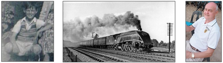
When I was a young boy around the age of 10, I have been fascinated by Steam Locomotives and still am at 82.
Image: Ben Brooksbank
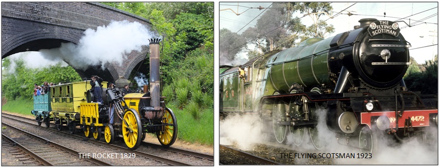
One of the first recognised successful Steam Locomotive was invented in England by George Stevenson called the ‘Rocket’. Locomotives are also referred to as ‘Engines’ and ‘Trains’ that pull the Trains. A Train is a combination of the Locomotive and Carriages or Wagons. Therefore we will use ‘Locomotive’ for this story. This was the real forerunner to the Steam Locomotives from the 1920’s to the1960’s in the United Kingdom as it used Pistons to drive the wheels. All Locomotives are classified by their wheel arrangement in this case O-2-2. Which means no small non driven front wheels (0) , Two Main Driving Wheels (2) using pistons and two small non driven rear wheels (2).
Image: The Rocket – British Railway Museum UK
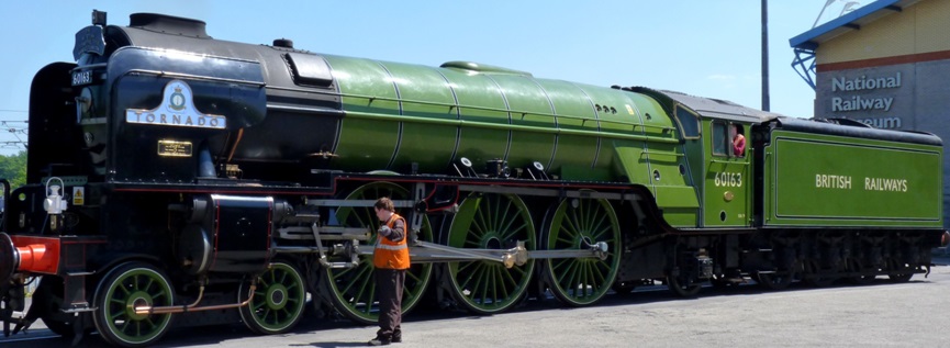
For example, a Steam Locomotive is still running today called the ‘Tornado’ which is last Steam Locomotive to be built in 2008 in the UK, wheel arrangement is 4-6-2. Which means four small non driven front wheels (4) , six Main Driving Wheels (6) using pistons and 2 small non driven rear wheels under the cabin (2). Each Locomotive has a specific Number in this case 60163 and on some Trains a name like this one ‘Tornado’. These are very important facts which relate to what is known as ‘Train Spotting’.
This Locomotive known as the ‘LNER Peppercorn Class A1’ was manufactured to the original design by Arthur Peppercorn in 1948. However, there were many different Locomotives in terms of size, design and configuration. The Railway in the UK in the 1950’s , 1960’s consisted of 4 main railway networks, The London and North Eastern Railway (LNER), London, Midland and Scottish Railway (LMS), Great Western Railway (GWR) and the Southern Railway (SR). They all became part of British Railways (BR).
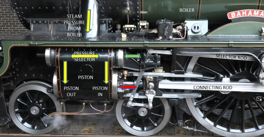
The Steam Locomotive Basic Operation
The Basic Operation of a Steam Locomotive is simple.
The Boiler is heated using coal to produce High Pressure Steam.
The High Pressure Steam is fed to the Pressure Selector
This Pressure Selector driven by the Selector Rod connected to the Main Driving Wheels directs the High Pressure Steam to one side of the Piston which makes the Piston go Out and then directs the High Pressure Steam to other side of the Piston which makes the Piston go In.
This then moves the Connecting Rod which is connected to the Main Driving Wheels.
If the Piston goes Out and In once it moves the Main Driving Wheels one revolution. However in practical terms this is far more complex.
The Steam Locomotive needs to be controlled by qualified Drivers . Another important person who is part of the Locomotive Crew is the Fireman who has to keep providing Coal from the ‘Tender’ at the back of the Cabin to the Firebox which heats the Water . He has to ensure the Water supply to the Boiler from the Tender is correct and that the High Steam Pressure is maintained at all times.
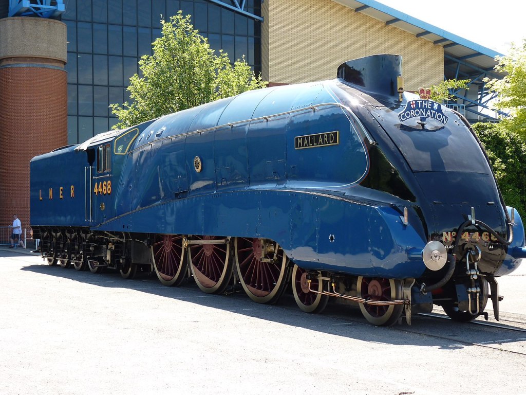
The Steam Train World Speed Record
The Steam Locomotive is in fact a magnificent machine which was adopted world wide. The engineering design and manufacture was second to none in the UK. The ‘Mallard’ an LNER Class A4 Pacific class 4468 4-6-2 designed by Sir Nigel Greasley created the worlds speed record of any Steam Locomotive Passenger Train of 125 mph which still stands today. I as a boy at Newcastle Central Station had the privilege of controlling the Mallard on the footplate with the driver for a few yards on its way to London whilst Train Spotting.
National Railway Museum York England
Goods Locomotives and Trains
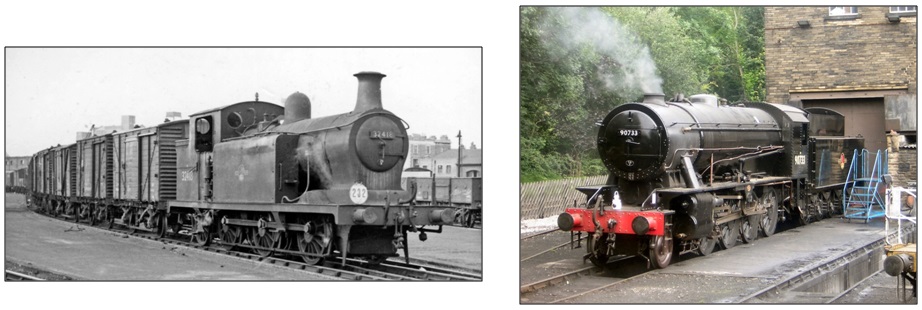
Locomotives were used for Passengers and Goods Trains as most of these were very busy as roads were still the there early part of construction. The Goods Trains used small Locomotives for shunting that is moving Goods Wagons to build a Train to go to different destinations in the UK. The mage is ( 32413, 0-6-2). The large Locomotives then moved the Goods Train to the Destinations. These included the War Department Locomotives like the preserved ‘Austerity’ 90733 2-8-0 which were used during the war 1943 to 1945 for Military transport. There were 935 produced the most of any Steam Locomotive in the UK.
Image: Ben Brooksbank Image: Worth Valley Railway
Passenger Locomotives and Trains
The most famous Passenger Locomotive is the ‘Flying Scotsman’ A1 class 60103 4-6-2 which was built in 1923 in Doncaster Yorkshire, 100 years ago and it is still Operating for pleasure Steam Train Journeys in the UK today. The Image shows the Flying Scotsman Locomotive pulling the Train called the Flying Scotsman with Standard Carriages .There were many different types of Passenger Locomotives but for the Main Lines these were the larger ones like The Mallard and Flying Scotsman.
Image: Geof Sheppard
The most famous UK Passenger Trains which consists of high quality Carriages is the ‘Pullman’. These are special Trains ‘First Class’ only that are used for long journeys such as London to Edinburgh on the LNER line. They were also the fastest Trains with very few stops on the way. In 1969 returning from Singapore I traveled from London to Newcastle on the London to Edinburgh Pullman Train which only took just over 3 hours. Today there are still Pullman Trains used for pleasure Train Journeys pulled by Steam and Diesel Locomotives.
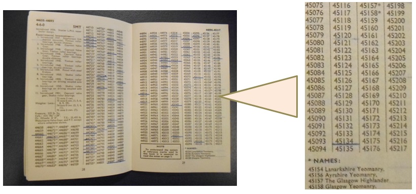
Train Spotting
From the age of 10 in 1951, I was fascinated by Steam Locomotives as a machine but more to do with there Numbers and Names as I started my hobby ‘Train Spotting’. At that time many boys and girls had a passion for looking at Locomotives and referring their number and name to a ‘Train Spotting Book’ which contained almost all the UK Locomotive Numbers and Names. The idea was to spot a Locomotive and then mark you Book to say that you had spotted that particular Locomotive. At the time I lived very near the Railway Line and to Norwich Railway Station and we used to visit my home town in Gateshead which was very near Newcastle Central Railway Station where the LNER London to Edinburgh in Scotland used to stop. Train Spotting was a very popular hobby for children and adults as there was little or no TV or computers mobiles etc and it was very competitive to find out who had the most numbers or a particular special Locomotive.
Besides collecting the numbers it was also a social occasion as we would spend all day waiting for the Locomotives coming which allowed us to communicate with each other striking up friendships and camaraderie. Today there are still some Train Spotters but it has now evolved into taking photographs of Steam Locomotives and Trains at the Heritage Railways used for pleasure Train journeys.
Heritage Railways
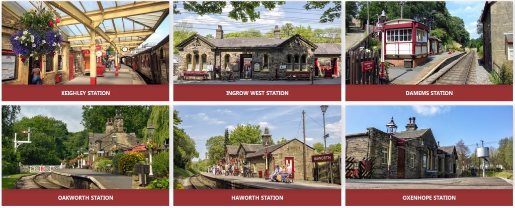
There are many Heritage Railways in the UK. As I used to Live in Keighley many years ago I am familiar with ‘The Keighley & Worth Valley Railway’ which is a 5-mile-long Heritage railway line in the Worth Valley, West Yorkshire, England, which runs from Keighley to Oxenhope. It connects to the National Rail network at Keighley railway station. This line and its Stations which are still in use were built in the 19th Century to serve the Mills a major source of employment. This railway is typical of many in the UK that have all types of Steam Locomotives and Trains for people to enjoy.
The Steam Age Attraction
Finally, today many thousands of people visit the Heritage Railways, Young and Old as the Steam Locomotive and the older type Carriages in particular seems to attract so many of us not just the nostalgia but the way in which the Steam Locomotives and Trains make strange noises letting off Steam and creating a lot of smoke that produces that special smell which affects you taste. Also being able to touch this magical Big Machine called the ‘Steam Locomotive’. Of course we all know that these are ‘dirty’ and ‘smelly’ but many of us still love them.
There is famous saying ‘Those Who Can’t Do, Teach’ emanating from the George Bernard Shaw’ 1905 stage play ‘Man and Superman’ is a complete fallacy and a great disservice to many of us who are Teaching and Training Professionals as well as, in my case, an ‘Aircraft and Avionic Engineering’ and ‘Information and ‘e’ Learning Technology’ Professional.
‘Teaching’ is related to theoretical and abstract, imparting knowledge and providing information.
‘Training’ is more Hands-On and Practical to develop abilities.
‘Technical Training’ in my case Aircraft and Aircraft Systems is in fact a combination of both ‘Teaching’ and ‘Training’.
However, Technical Training is just not theoretical, imparting information and knowledge it is also the ability to apply that knowledge to practical operations of systems and the ability to diagnose and repair faults that may occur within a system. Those that carry out Technical Training are called ‘Instructors’.
Aircraft, especially the latest ones are a fully integrated machines that use a combination of systems electronic, electrical and mechanical all working in tandem with each other, controlled automatically and/or by the aircrew. Thats why we have several Instructors with different trade knowledge and experience such as Airframe, Engine, Electrical and Avionic Engineers working as a team to ensure we cover all aspects of an Aircraft’s operation and maintenance.
Training Sequencing
The Challenge of a Training Professional is to make complex systems appear to be simple to the students by explanation and reference to previous theoretical knowledge gained by the student.
The first and most important issue for Technical Training is the sequencing of the theoretical fundamental knowledge and information in a way that it provides the building blocks to which the student can refer as they progress through their Training Cycle.
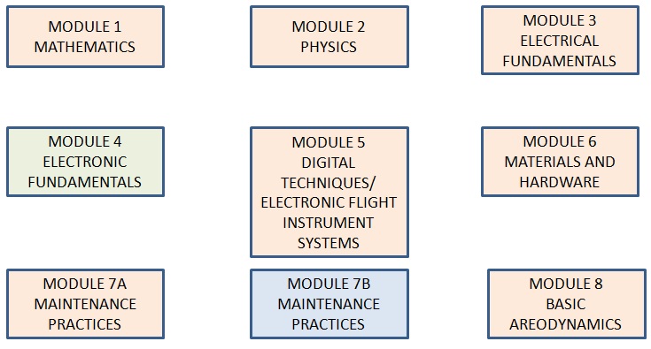
A prime example is the numbering of the Modules and Sub- Modules of the European Union Aviation Safety Agency (EASA) Part 66 Aircraft Maintenance Engineering Licence program syllabus, adopted by the many Civil Aviation Authorities including the Civil Aviation Authority of Malaysia (CAAM).
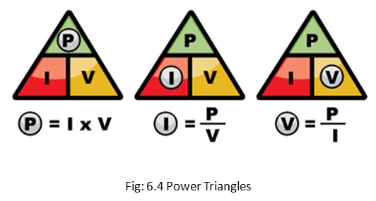
This simplified diagram shows that before students begin their more complex Aircraft Systems Training they have to learn the Fundamentals first which provides the building blocks they need in the sequence from Modules 1 to 8 except Module 4 for Avionic students and Module 7B for mechanical students.
The more complex theoretical Modules 9 to 17 are completed after Modules 1 to 8.
Training Synchronisation
Having achieved the correct sequencing of Training the next important aspect is the Media used to support the Training. It is of utmost importance that the Media is totally Synchronised. What does that mean? It is essential that the content especially the Graphics of the Training Notes should be Identical with Identical Figure Numbers to that incorporated in the Presentation Media such as Power Point Presentations. This is known as Synchronisation. The main reason is that whilst the Instructor is explaining the content on the Presentation Graphic the student can follow in their Training Notes Graphic.
As I have produced or upgraded 80% of the CAAM Modules including Training Notes and Power Point Graphics and Presentations, I am fully aware of the need to simplify information whilst retaining its Validity and Synchronising it as detailed above . This extensive task took me 7 years from 2013 to 2020 to complete.
Training Presentation
Training Presentation can take several forms including:
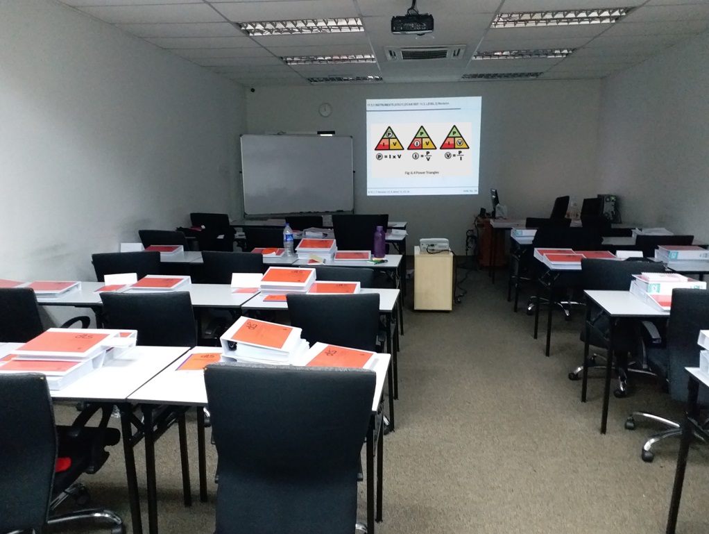
Classroom collective learning with the aid of an Instructor and a large display screen and white board.
Classroom collective learning but using individual computer systems to allow students to learn without the aid of an Instructor.
Self learning outside of a classroom environment accessing the Internet using computers or hand held devices such as Mobiles and Pads.
Each of these options have there advantages and disadvantages but in this case I want to consider the first option, which having many years experience in Technical Training Design and as an Instructor, I believe to be the most effective.
However, there is a caveat to that belief which concerns the quality of the of the Presentation Media and information that is used for the Presentation and the quality of the Instructor who is Presenting the Technical Training.
Presentation Media
As we have already discussed that the Training Media must be Synchronised at all times. However, some may think that my Presentation should include the Training Notes Text word for word, which I have seen. This is in my opinion totally wrong both visually and as a training technique, as the Presentation Media should be primarily be based upon Graphical Images and/or Animations with the minimum amount of Text excluding Labels.
Why Graphics? It has been scientifically proven that most of our learning comes from our Vision. There is a saying which is true ‘A Picture is worth a thousand Words’. What some do not realise Text is in fact a Picture but a very complicated one which must be interpreted. Therefore a Graphical Picture on screen without Text is much easier for us to interpret.
Another Presentation technique is to ‘Build-Up’ an Image such as a Block Diagram in steps which avoids the brain having to take in all of the information at once. However, this may not be possible due to time constraints for the lesson.
Technical Training Instructors
High Quality Technical Training Instructors are a those that have the two main qualities.
An in depth knowledge and experience of the subject matter being presented to the student.
Have the ability and skills to present the subject matter in a manner that motivates the students to learn, is accurate and interesting using the the correct ‘Training Techniques’.
However, this is not always the case as some Instructors have the knowledge and experience but are unable transfer that to the students correctly. Some have the ability to transfer the information to the student but lack the in depth knowledge and experience to transfer the correct Technical content. Both of these cases are detrimental to Technical Training, however sadly there are many cases that I have experienced in my long Technical Training career.
I was very fortunate to have received an ‘Instructional Techniques’ course and later a ‘Management of Training’ course being the in the Royal Air Force (RAF) as an RAF ‘A’ Class Instructor and Officer In Charge of a RAF Harrier Aircraft School. I was a Senior Training Officer at British Aerospace (BAe). After 18 months at BAe I started by own Computer Based Training (CBT) business in 1988 developing e Learning for the RAF Harrier and Tornado Aircraft which I had extensive maintenance and operational knowledge and experience. My final project was as a Training Consultant from 2013 to 2020 at a CAAM School In Malaysia. ( See my previous posts).
Training Aids
Technical Training can be enhanced significantly by using what is known as Training Aids. This term can relate to very simple additional information by the Instructor on a white board to complex Training Rigs used to demonstrate systems and sub-systems. Showing individual real components in the classroom to support the lesson are very valuable Training Aids. I have created many Training Aids some of which were very complex but it made the students understanding much easier. I have used an ‘off the shelf ‘ MS Flight Simulator to show the fully animated operations of the Boeing B777 Aircraft and its Avionic Displays in ‘real time’ whilst in flight during the lesson and as consolidation of the Avionic Avionic Displays information.
Instructor Student Interface
One of the most important part of Technical Training is the Interface between the Instructor and the Student. In the majority of cases Technical Training is related to the future or present Occupation the student may have, therefore it is vitally important that the student has confidence in what information is being provided to them by the Instructor.
Today it is so important for the Instructor to know what he is teaching the students is technically sound, as they will also have the ability to go to the internet to confirm what they are being told is correct or otherwise. However, after a short while they will judge the Instructors not just on their technical knowledge but how that information has been presented and explained to them by the Instructor. This feedback is normally an ‘Instructors Assessment Form’ that the students are required to complete.
There have been many times where the students judge one Instructor against another Instructor and provide feedback which can be positive and negative. That is why I have been involved in regular formal Instructor Performance Assessment both in the RAF and as a Consultant for the CAAM School which is vital for the Training Organisation. This involves sitting in the classroom with the students assessing, the Instructors Instructional Techniques, Interface with the Students and Technical Correctness. This Performance Assessment can be planned and/or impromptu depending upon the results from previous Assessments and any corrective action that has been suggested to the Instructor after the previous Assessment. This is a ‘Formal Assessment’ and all details comments are to be recorded on a Form or as a Report.
Student Assessment
Finally is the Students Assessment which can be informal or formal. The purpose of Student Assessment is to measure the amount that the students have learnt.
Informal Student Assessment is normally based upon ‘Question and Answer’ sessions within the classroom during and after the lesson, which gives the Instructor feedback to measure what the students are learning. Another form of informal assessment is to provide the students with a ‘Mock Examination’ based upon the type of questions they may be asked on their formal examination.
Formal Student Assessment is designed to ensure that the student has learnt sufficient to obtain a set ‘Pass Mark’ which can vary in different organizations but is normally around 70% to 75%. These examinations will determine whether the Student will achieve the overall standard required by the Authority, in the case of Aircraft Systems in Malaysia CAAM. Given that the student achieves the required standard the they will be given a formal certificate which is recognisable in law.
When you consider the name ‘Multimedia’ is common place today and most people have an understanding what it means, combining text, graphics, animation, video and audio and virtual reality to produce a visual and audio presentation on computers, mobiles, laptops and pads.
In August 1988, 35 years ago, when I started my company, as an ex Royal Air Force (RAF) aircraft and avionics engineer, called Computerised Training Systems Ltd, there was no ‘Multimedia’ and in fact I was one of the first people and my small team to create the very early forms of ‘Multimedia’ in Lincolnshire, England, United Kingdom for Technical Training which is the basis of what we have throughout the world today.
CTS started at the Queensway Business Centre Scunthorpe 8.8.1988CTS expanded in 1990 to Duke House, Queensway Scunthorpe (Day One)
It may seem very hard for people to accept that only 35 years ago that the Computer was still in its early stages of development both in Hardware and Software terms. This included the Computer Operating Systems (OS) software and the software application tools for creating graphics and animation. Another important aspect was that there were no Computer systems that could directly show video or video combined with graphics overlays.
In 1988 there were two main Computer System types, the ‘IBM Personal Computer (PC)’ and the ‘Apple and Commodore’ Computers. These two systems were different in many ways. I chose the Commodore Computer Systems for my initial Technical Training Systems that was my vision as an experienced Technical Training Designer and Senior Instructor.
The Commodore Computers however were the more advanced Computers. Unlike the IBM these Computer Displays were full colour 16.8million colours. It had a high quality stereo audio facility. The Operating system was based upon a ‘Windows’ concept and were ‘Multi Tasking’. This was very important as there was a Central Processor Unit (CPU) Motorola 68000 32 bit, but also additional Processors dedicated to functions such as the graphics display and audio. This meant that the processors worked together on there respective tasks. The input devices included a keyboard, mouse and input/output RS 232 communication ports and other output ports. The 3,5 inch Floppy Disc was the main source of data storage but the later Amiga Computers would have a SCSI Hard Disc Drive. The application software such as ‘D Paint’ for graphics and others for animation and audio were basic but could produce some good results. The standard output display at that time was PAL 640 x 512 pixels the European video standard. The initial Commodore Amiga A 1000 and later Computer models were made in Germany. The A1000 was the first Commodore Amiga I saw which was being used to design Avionic Graphics Display systems.
However, in terms of sales and global support the IBM PC was predominant and became an industry standard as most of the Computers at this time were designed for business applications and not ‘Multimedia’ as it did not exist. The Commodore Amiga, A500 Computer was based upon ‘Graphics and Animation Applications’ with the A500 designed primarily for the ‘Games Market’. In early 1987 the Commodore Amiga A 2000 was launched which had advance facilities and expansion slots which could house a PC Compatibility Card and a 5.25” Drive for the PC discs, enabling it to display both Amiga and basic PC graphics. In 1988 the A2000 was upgraded with a SCSI 9 M/Byte Hard Disc Drive and controller. However, in comparison the prices of the Amiga A500 and A2000 package were far lower than the IBM PC’s and at the same time the capabilities of the Commodore Computers were far in advance of the IBM PC for my requirements.
The Creation of my vision of a Multimedia System – Commodore Amiga Technology
In the initial years of my company It was the Amiga A500 and A2000 that were the basis of the Multimedia Systems and Software which my team and I would design and create. The Amiga A2000 was used for the Development of the Training Software called Courseware a name I created from Training COURSE SoftWARE and is still used today. The creation of the graphics was vitally important for the Technical Training programs we would produce. In particular the Amiga allowed us to produce electrical and fluid flows that could be controlled an colours changed instantly when instructed to do so. In addition we could animate control valves, parts of mechanisms and electrical switches on control panels at the same time as the flows were activated (in real time).
I decided that the Amiga A500 Computer Systems would be used for the individual students in the Classroom. These were loaded with each lesson on the 3.5”floppy discs. The student could then activate the Training Software themselves using the mouse.
The Classroom Presentation System was also unique as I was able to design a system that connected the Amiga A 2000 to a large overhead Projector onto a Large Screen which replicated the Training Software for use by the Instructor.
Whilst the Commodore Amiga was an important platform for my vision of Multimedia Training it alone could not produce the Multimedia that I required. This included the integration of Video Tapes using a Sony U-Matic 9600 Video Recorder/Player and the ability to Overlay Text onto the Video at the same time on the display screen. The UMatic Video Recorder/Player was a high quality system using 3/4” tape but most importantly could be controlled via a RS 232C port. Therefore the Display issue and U-Matic control issue had to be solved.
At this time I was fortunate to have a contact in central England who was working with Commodore UK in developing an external ‘Genlock’ for a completely different reason. However after discussions the contact was able to produce a bespoke ‘Genlock’ for my company to enable me to physically overlay text on the video at the same time as the video from the U-Matic was being displayed.
Although this would solve the Hardware issue the Software for both the implementation of the Text Overlay and Control of the U-Matic still had to be solved.
My company had its own Software known as an ‘Authoring Software’ which enabled us to program our Training Software using a set of specific commands. I called this Authoring Software ‘ASTRA’ which was developed and supported by one of my team specialist for the Commodore Amiga. After considering the requirements we included the commands for the Text Overlay and the control of the U-Matic Video Recorder/Player. The U-Matic control allowed us to search and play sequences using the ‘Frame Code Numbers’ which the UMatic system operated on using commands via the Computer RS 232C port and cable connection to the U-Matic RS232C input port.
We had now developed the foundation of a Multimedia System including the ‘U-Matic 9600 Video Tape Player’ connected to the ‘bespoke Genlock’ which is connected to the ‘Commodore Amiga A2000’ which is then connected to an ‘Overhead Projector’ all controlled by our companies ‘Courseware’.
Although I had developed the major Multimedia System this had to be integrated with other existing media systems to allow the Technical Instructors full flexibility in what they could present to the students. Many of the existing lessons were presented with static Overhead Projection Slides and 35mm slides using a slide projector. In addition I also wanted to integrate a new Canon Camera RC-251 ION and the Player RV-301 technology for them to be able to show the whole class close-ups of items of equipment.
I therefore designed and built a Total Multimedia Presentation System Unit that integrated all of the sub systems outlined above. The complete Presentation System was the connected to the Overhead Projector for a big screen display.
Total Multimedia Presentation System Units and the Two Screen Multimedia Presentation System Units proved to be very useful and the Instructors were very impressed being able to have Courseware having good quality graphics of systems with animated actions of components and systems with animated flows of technical systems combined with Integrated Video sequences when activated. This in addition to their existing media.
However, as an aircraft engineer I also wanted to create a Student System that reflected each part of a system when it was activated. This required a ‘Four Screen’ system each showing its part of the system being operated. This system used 4 x Amiga A500 Computers all communicating with each other using our specialised ASTRA Courseware. This was designed for two students observing the effect on a system and a component within that system at the same time.
However this was never used by a customer due to a company change in technology forced upon us due to the customers policy of wanting IBM PC technology in preference to Commodore Amiga technology not because the Amiga technology was not good.
The Creation of a new Multimedia System – IBM PC Technology
By 1991/1992 PC technology had advanced at an unprecedented rate by the introduction of the Intel i386 Processor quickly followed by the i486 Processor. This allowed processing speeds of up to a 50 million instructions per second. The PC-486GR was standard equipped with a high-resolution graphics board, and it rendered both text and graphics at high speeds thanks to the development of a high-speed video ASIC that provided a no-wait Windows environment. This was far in advance of the AT 286 that was available in 1988 and the possibility of replacing the Amiga performance for Graphics and Animation in full colour modes. In addition to the Hardware advances there were now many third party application software for graphics, animation and audio production.
The question asked by our major customer was two fold. One could we provide the new PC 486 Computer Multimedia Systems and develop new Courseware to run on them and secondly could we convert existing Commodore Amiga Courseware to run on the new PC 486 Multimedia Systems. What a Challenge !!! however the answer had to be ‘Yes’ but I had to solve these problems with my team and do it as soon as we could.
In terms of the Hardware there was very little problem, but the Operating System would be the new PC Windows. For us to be able to make any Courseware operable it would be essential to create a modified ASTRA Authoring System into a ASTRA for Windows Authoring System but this would take some time.
Demonstration of the new PC 486 Computer Hardware and Courseware
Operating the Singapore Airlines Hardware and Courseware Systems provide to them.
As we progressed and the market for Courseware expanded due to the success of us the forerunners. The number of competitors started to grow especially now that the PC had taken over the Multimedia market. However, our company gained major Contracts in South East Asia and from our major customer in the UK for our PC Systems and Courseware. Today like many other companies in this field I closed my final company Computerised Training Systems Sdn Bhd in Malaysia in December 2021. A new breed of companies creating new technologies are moving forward at a great rate just as we in the eighties and nineties did. I feel very proud of all my team workers over the years who helped in the advancement of our technologies and innovations which contributed in a small way to the state of technologies we have today.
It was a fantastic and technically challenging journey which I feel very fortunate to have been involved. Looking back aged 82 it was a major part of my life as you can see in the image it was so satisfying and memorable.
My passion for Technical Training started whilst in the Royal Air Force (RAF) in Singapore RAF Seletar between 1966 to 1969. Since then I have been involved in RAF Training Design, Instruction and the Management of an RAF Training School as the Officer In Charge. I Created of a company in 1988 to 2021, Designing and Developing Computer Based Training (e learning) for Military and Civil Aircraft in the UK and Singapore and completely Redesigning and Developing EASA and CAAM Part66 Training Media for all Avionic Modules and Helicopter Modules for A, B1 and B2 students in Malaysia until 2021. This is just a very very small example of the subject matter.
Electrical Fundamentals – Direct Current (DC) Circuits
A Direct Current (DC) Circuit is a combination of electrical components that are connected together to perform a specific electrical function using a Direct Current source.
A DC Circuit Diagram is a graphical representation of the electrical components and their values to enable the DC Circuit to be designed for specific , Voltage, Current and Power consumption and the physical construction of the electrical components.
The technology today combines many thousands of electrical components into Microchips also known as Integrated Circuits. However, it is important to allow you to learn the basic fundamentals of a DC Circuit, we will be using simplified DC Circuit Diagrams.
A SERIES CIRCUIT – is one continuous connection (path) of components to a DC source. This diagram shows three Resistors connected in series to a Battery.
A PARALLEL CIRCUIT – has more than one path of components to a DC source. This diagram shows three Resistors connected in parallel to a Battery.
A COMBINATION CIRCUIT of both Series and Parallel circuits. This diagram shows three Resistors connected in parallel which are connected to two Resistors in series to a Battery.
We will consider these three options for both the design and calculation of Resistance (R) Voltage (V), Current (I) and Power (P) using the Electrical Laws defined by:
Ohms Law, Kirchhoff’s Current Law (First Law) and Kirchhoff’s Voltage Law (Second Law) which we will consider in more detail.
OHMS LAW: (Georg Ohm)
The amount of Current (I) is directly proportional to the Voltage (V) and inversely proportional to the Resistance (R).
KIRCHOFFS CURRENT LAW (FIRST LAW): (Gustav Kirchoff)
At any Node (Junction) in an Electrical Circuit, the sum of the Currents (I) flowing into the Node is equal to the Sum of the Currents flowing out of that Node, or: The algebraic Sum of the Currents in a network of Conductors meeting at a point is Zero.
KIRCHOFFS VOLTAGE LAW (SECOND LAW): (Gustav Kirchoff)
The Sum of the Electromotive Forces (EMF’s) in any closed loop is equivalent to the Sum of the Potential Drops (PD) Voltages in that loop, or: The algebraic Sum of the products of the Resistances of the Conductors and the Currents in them in a closed loop is equal to the Total EMF available in the loop.
RESISTORS & SYMBOLS
We will consider Resistor (R) components first for the basic DC Circuit configurations and calculations. These are typical DC Circuit symbols which relate to physical components.
Main Source of DC Power
The BATTERY – These can be very large with a DC high power output down to very small batteries with a small DC power output for watches etc. There can be a single or multiple Batteries in a DC Circuit.
The DC GENERATOR – These vary in size and DC power output.
The TRANSFORMER /RECTIFIER – DC power varies with design and size but you will recognise these as your mobile charger.
Electromotive Force (EMF)
Electromotive Force is provided by the Power Source such as Batteries which provides the Voltage to the DC Circuit. In this case a single battery will produce and EMF of 1.5 Volts and four Batteries connected in Series will produce an EMF of 6 Volts. On the DC Diagrams which will follow the Battery Symbols will be allocated an EMF Voltage.
The EMF Voltage is important when we relate it to Kirchoffs Voltage Law (Second Law) as you will see later.
Ohms Law – Practical Application
The amount of Current (I) is directly proportional to the Voltage (V) and inversely proportional to the Resistance (R). This is represented as a triangle.
Voltage (V) is measured in Volts (V), Resistance (R) is measured in Ohms (Ω) and Current(I) is measured in Amperes (A) also referred to as Amps.
The DC Circuit represents Ohms Law and the simple formulae where the Battery produces an EMF of 32 Volts (V) and the Resistor (R) has a resistance of 16 Ohms (Ω) which creates a Current (I) of 2 Amps (A).
Whenever the value of the Voltage (V) or Resistance (R) is changed it will automatically update the Current (I) flow.
We refer the Total Resistance (R) of the DC Circuit as the ‘Load’ in this case 16Ω.
Electromotive Force (EMF) and Potential Drop (PD)
Both EMF and PD are measured in Volts (V). The main difference is that the EMF is the Electromotive Force produced by the DC Power applied to the Circuit in this case a Battery (32 Volts) and the PD the Potential Drop measured across the component in this case the Resistor which is 32V. PD is also referred to as the Potential Difference.
Kirchoffs Voltage Law
Kirchoffs Voltage Law basically means that the sum of all the PD’s across the components must equal the EMF Voltage whatever the values of Resistance (R) and Current (I). Using Ohms Law the PD across each of the two Resistors is 16Volts which equals the EMF of 32 Volts.
Kirchoffs Current Law
Nodes
A Node in a DC Circuit is any point that Current (I) enters a Component or Junction of Components and leaves a Component or Junction of components.
In a Series DC Circuit as shown, this is a very simple example which shows that Current entering and leaving a Node is 1 Amp. We will consider more complex DC Circuits later but the principle is identical.
Power Provision and Consumption
Later in this series we will discuss Power in more detail but to complete the DC Series Circuits we will consider Power related to what we have discussed already.
Power (P) Is measured in Watts (W). Remember we said that all PD Voltages equals the EMF Voltage. Power is similar in that all Power (P) consumed by the DC Circuit Components will equal the Power (P) provided by the EMF. We calculate Power using a simple formula represented as a triangle.
Using the formulae above the DC Circuit shows that the Power (P) consumed by each of the two the Resistors (R) is 16 Watts (1A x 16V) which is a total of 32 Watts which the EMF is providing.
However, it must be emphasised that the EMF will have a limited Power in Watts that it can supply, therefore DC Circuits must be designed to consume Power (P) that is within the limit of the EMF Power Source.
Total Resistance (Ω) and Effects: Series DC Circuit
To calculate the Total Resistance (Ω) of a SERIES DC Circuit we use the following formula:
The Total Resistance (Ω) = R1+R2+R3 = 150(Ω).
Effects
This is the effect of the Resistances on this DC Circuit
The Total Current (I) = 300V/150(Ω)=2Amps.
The EMF 300V = Total PD’s = R1 30×2=60V + R2 100×2=200V + R3 20×2=40V
The EMF Power (P) = 300V x 2A= 600 W.
The Total Power Consumed 600W= R1 30×2=60W + R2 100×2=200W+ R3 20×2=40W
Application of the Electrical Fundamentals you have learnt to a Parallel DC Circuit.
Total Resistance (Ω) and Effects: Parallel DC Circuit
To calculate the Total Resistance (Ω) of a PARALLEL DC Circuit we use the following:
Parallel Formula: To produce and equivalent Series Resistor Value:
The Total Resistance (Ω) = 1/R1+1/R2+1/R3 = 1/20+1/40+1/20 = 2/40+1/40+2/40 =5/40 RT 40/5 = 8(Ω).
The Total Current (I) = 40V/8(Ω) = 5Amps.
The Current (I) through each Parallel Resistor (R) is inversely proportional to the value of Resistance.
The EMF 40V = Total PD is 40V as all 3 Resistors are in Parallel therefore we use the Nodes shown, as these are the Junctions where the total Current (5A) goes in and comes out.
The EMF Power (P) = 40V x 5A= 200 W.
The Total Power Consumed 200W= R1 40Vx2A=80W + R2 40Vx1A=40W+ R3 40Vx2A=80W.
Application of the Electrical Fundamentals you have learnt to a Combined Series, Parallel DC Circuit.
Total Resistance (Ω) and Effects: Series, Parallel DC Circuit.
To calculate the Total Resistance (Ω) of a SERIES,PARALLEL DC Circuit we use the following formulae:
Parallel Formula: To produce and equivalent Series Resistor Value: