
My passion for Technical Training started whilst in the Royal Air Force (RAF) in Singapore RAF Seletar between 1966 to 1969. Since then I have been involved in RAF Training Design, Instruction and the Management of an RAF Training School as the Officer In Charge. I Created of a company in 1988 to 2021, Designing and Developing Computer Based Training (e learning) for Military and Civil Aircraft in the UK and Singapore and completely Redesigning and Developing EASA and CAAM Part66 Training Media for all Avionic Modules and Helicopter Modules for A, B1 and B2 students in Malaysia until 2021. This is just a very very small example of the subject matter.
Electrical Fundamentals – Direct Current (DC) Circuits
A Direct Current (DC) Circuit is a combination of electrical components that are connected together to perform a specific electrical function using a Direct Current source.
A DC Circuit Diagram is a graphical representation of the electrical components and their values to enable the DC Circuit to be designed for specific , Voltage, Current and Power consumption and the physical construction of the electrical components.

The technology today combines many thousands of electrical components into Microchips also known as Integrated Circuits. However, it is important to allow you to learn the basic fundamentals of a DC Circuit, we will be using simplified DC Circuit Diagrams.

A SERIES CIRCUIT – is one continuous connection (path) of components to a DC source. This diagram shows three Resistors connected in series to a Battery.

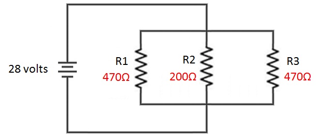
A PARALLEL CIRCUIT – has more than one path of components to a DC source. This diagram shows three Resistors connected in parallel to a Battery.
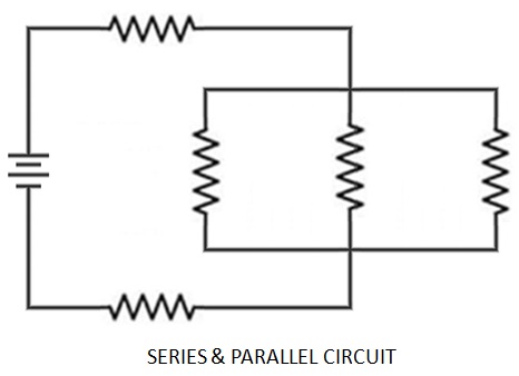
A COMBINATION CIRCUIT of both Series and Parallel circuits. This diagram shows three Resistors connected in parallel which are connected to two Resistors in series to a Battery.
We will consider these three options for both the design and calculation of Resistance (R) Voltage (V), Current (I) and Power (P) using the Electrical Laws defined by:
Ohms Law, Kirchhoff’s Current Law (First Law) and Kirchhoff’s Voltage Law (Second Law) which we will consider in more detail.

OHMS LAW: (Georg Ohm)
The amount of Current (I) is directly proportional to the Voltage (V) and inversely proportional to the Resistance (R).

KIRCHOFFS CURRENT LAW (FIRST LAW): (Gustav Kirchoff)
At any Node (Junction) in an Electrical Circuit, the sum of the Currents (I) flowing into the Node is equal to the Sum of the Currents flowing out of that Node, or: The algebraic Sum of the Currents in a network of Conductors meeting at a point is Zero.

KIRCHOFFS VOLTAGE LAW (SECOND LAW): (Gustav Kirchoff)
The Sum of the Electromotive Forces (EMF’s) in any closed loop is equivalent to the Sum of the Potential Drops (PD) Voltages in that loop, or: The algebraic Sum of the products of the Resistances of the Conductors and the Currents in them in a closed loop is equal to the Total EMF available in the loop.
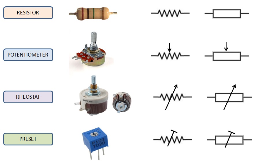
RESISTORS & SYMBOLS
We will consider Resistor (R) components first for the basic DC Circuit configurations and calculations. These are typical DC Circuit symbols which relate to physical components.
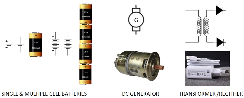
Main Source of DC Power
The BATTERY – These can be very large with a DC high power output down to very small batteries with a small DC power output for watches etc. There can be a single or multiple Batteries in a DC Circuit.
The DC GENERATOR – These vary in size and DC power output.
The TRANSFORMER /RECTIFIER – DC power varies with design and size but you will recognise these as your mobile charger.

Electromotive Force (EMF)
Electromotive Force is provided by the Power Source such as Batteries which provides the Voltage to the DC Circuit. In this case a single battery will produce and EMF of 1.5 Volts and four Batteries connected in Series will produce an EMF of 6 Volts. On the DC Diagrams which will follow the Battery Symbols will be allocated an EMF Voltage.
The EMF Voltage is important when we relate it to Kirchoffs Voltage Law (Second Law) as you will see later.

Ohms Law – Practical Application
The amount of Current (I) is directly proportional to the Voltage (V) and inversely proportional to the Resistance (R). This is represented as a triangle.
Voltage (V) is measured in Volts (V), Resistance (R) is measured in Ohms (Ω) and Current(I) is measured in Amperes (A) also referred to as Amps.

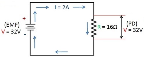
The DC Circuit represents Ohms Law and the simple formulae where the Battery produces an EMF of 32 Volts (V) and the Resistor (R) has a resistance of 16 Ohms (Ω) which creates a Current (I) of 2 Amps (A).
Whenever the value of the Voltage (V) or Resistance (R) is changed it will automatically update the Current (I) flow.
We refer the Total Resistance (R) of the DC Circuit as the ‘Load’ in this case 16Ω.
Electromotive Force (EMF) and Potential Drop (PD)
Both EMF and PD are measured in Volts (V). The main difference is that the EMF is the Electromotive Force produced by the DC Power applied to the Circuit in this case a Battery (32 Volts) and the PD the Potential Drop measured across the component in this case the Resistor which is 32V. PD is also referred to as the Potential Difference.
Kirchoffs Voltage Law
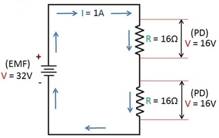
Kirchoffs Voltage Law basically means that the sum of all the PD’s across the components must equal the EMF Voltage whatever the values of Resistance (R) and Current (I). Using Ohms Law the PD across each of the two Resistors is 16Volts which equals the EMF of 32 Volts.

Kirchoffs Current Law
Nodes
A Node in a DC Circuit is any point that Current (I) enters a Component or Junction of Components and leaves a Component or Junction of components.
In a Series DC Circuit as shown, this is a very simple example which shows that Current entering and leaving a Node is 1 Amp. We will consider more complex DC Circuits later but the principle is identical.

Power Provision and Consumption
Later in this series we will discuss Power in more detail but to complete the DC Series Circuits we will consider Power related to what we have discussed already.
Power (P) Is measured in Watts (W). Remember we said that all PD Voltages equals the EMF Voltage. Power is similar in that all Power (P) consumed by the DC Circuit Components will equal the Power (P) provided by the EMF. We calculate Power using a simple formula represented as a triangle.

Using the formulae above the DC Circuit shows that the Power (P) consumed by each of the two the Resistors (R) is 16 Watts (1A x 16V) which is a total of 32 Watts which the EMF is providing.
However, it must be emphasised that the EMF will have a limited Power in Watts that it can supply, therefore DC Circuits must be designed to consume Power (P) that is within the limit of the EMF Power Source.
Total Resistance (Ω) and Effects: Series DC Circuit
To calculate the Total Resistance (Ω) of a SERIES DC Circuit we use the following formula:
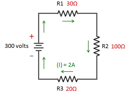
The Total Resistance (Ω) = R1+R2+R3 = 150(Ω).
Effects
This is the effect of the Resistances on this DC Circuit
The Total Current (I) = 300V/150(Ω)=2Amps.
The EMF 300V = Total PD’s = R1 30×2=60V + R2 100×2=200V + R3 20×2=40V
The EMF Power (P) = 300V x 2A= 600 W.
The Total Power Consumed 600W= R1 30×2=60W + R2 100×2=200W+ R3 20×2=40W

Application of the Electrical Fundamentals you have learnt to a Parallel DC Circuit.
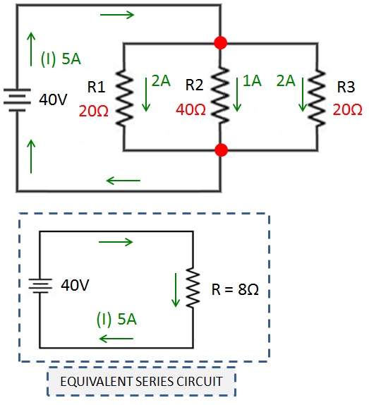
Total Resistance (Ω) and Effects: Parallel DC Circuit
To calculate the Total Resistance (Ω) of a PARALLEL DC Circuit we use the following:
Parallel Formula: To produce and equivalent Series Resistor Value:
The Total Resistance (Ω) = 1/R1+1/R2+1/R3 = 1/20+1/40+1/20 = 2/40+1/40+2/40 =5/40 RT 40/5 = 8(Ω).
The Total Current (I) = 40V/8(Ω) = 5Amps.
The Current (I) through each Parallel Resistor (R) is inversely proportional to the value of Resistance.
The EMF 40V = Total PD is 40V as all 3 Resistors are in Parallel therefore we use the Nodes shown, as these are the Junctions where the total Current (5A) goes in and comes out.
The EMF Power (P) = 40V x 5A= 200 W.
The Total Power Consumed 200W= R1 40Vx2A=80W + R2 40Vx1A=40W+ R3 40Vx2A=80W.

Application of the Electrical Fundamentals you have learnt to a Combined Series, Parallel DC Circuit.

Total Resistance (Ω) and Effects: Series, Parallel DC Circuit.
To calculate the Total Resistance (Ω) of a SERIES,PARALLEL DC Circuit we use the following formulae:
Parallel Formula: To produce and equivalent Series Resistor Value:
The Parallel Resistance (Ω) = 1/R1+1/R2+1/R3 = 1/20+1/40+1/20 = 2/40+1/40+2/40 =5/40 RT 40/5 = 8(Ω).
Series Formula: To produce the Total Resistance Value: (R1,2,3) + R4 + R5= 8 +32 +20 = 60Ω
The Total Current (I) = 300V/60 (Ω) = 5Amps.
The Current (I) through each Resistor (R) is inversely proportional to the value of Resistance.
The EMF 300V = R4=32×5=160V, (R1,2,3)=8×5=40V, R5=20×5=100V
The EMF Power (P) = 300V x 5A= 1500 W.
The Total Power Consumed 1500W= R1 40Vx2A=80W + R2 40Vx1A=40W+ R3 40Vx2A=80W + R4 160Vx5=800W + R5 100×5 =500W.
That is the end of of this post I hope it has been helpful.
